


Quick Research
Generate reliable direction feasibility study reports for your R&D in just a few steps.

Technical Q&A
Discover and master advanced knowledge NOW. Basics, ideas, possibilities, all at once.

Find Solutions
As an expert in R&D theories, this can generate solutions to your technical problems instantly.

Evaluate Feasibility
Analyze your overall solution with one click, know your potential R&D risks in advance.

Monitor Landscape
Get weekly tech updates, stay abreast of the latest tech innovations and key insights.
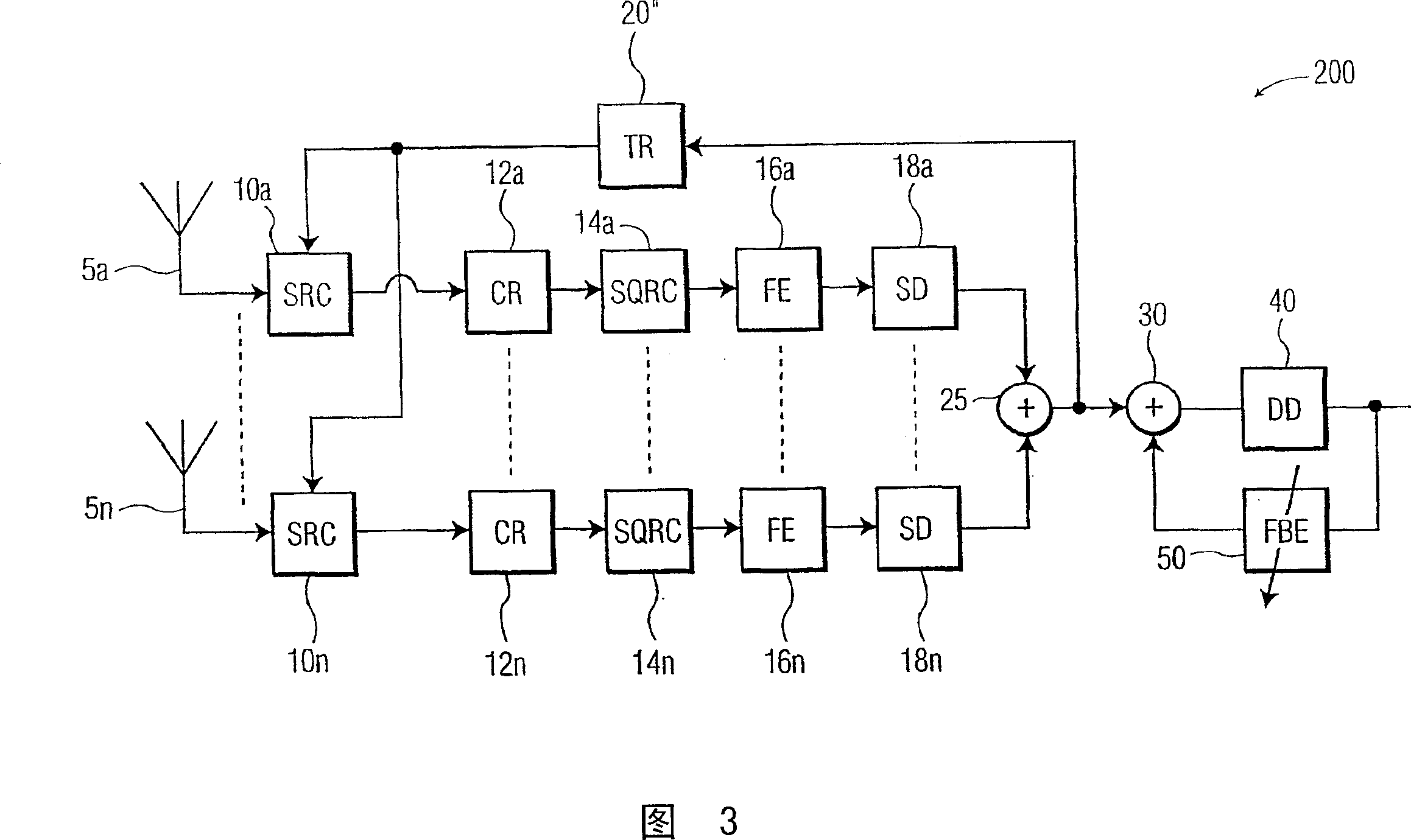
Joint timing recovery and equalization for an N-antenna system
A timing recovery, antenna technology, applied in diversity/multi-antenna systems, radio transmission systems, components of TV systems, etc., can solve problems such as receiver system performance degradation, TR algorithm unable to obtain synchronization lock, etc.
- Summary
- Abstract
- Description
- Claims
- Application Information
AI Technical Summary
Problems solved by technology
Method used
Image

Examples
Embodiment Construction
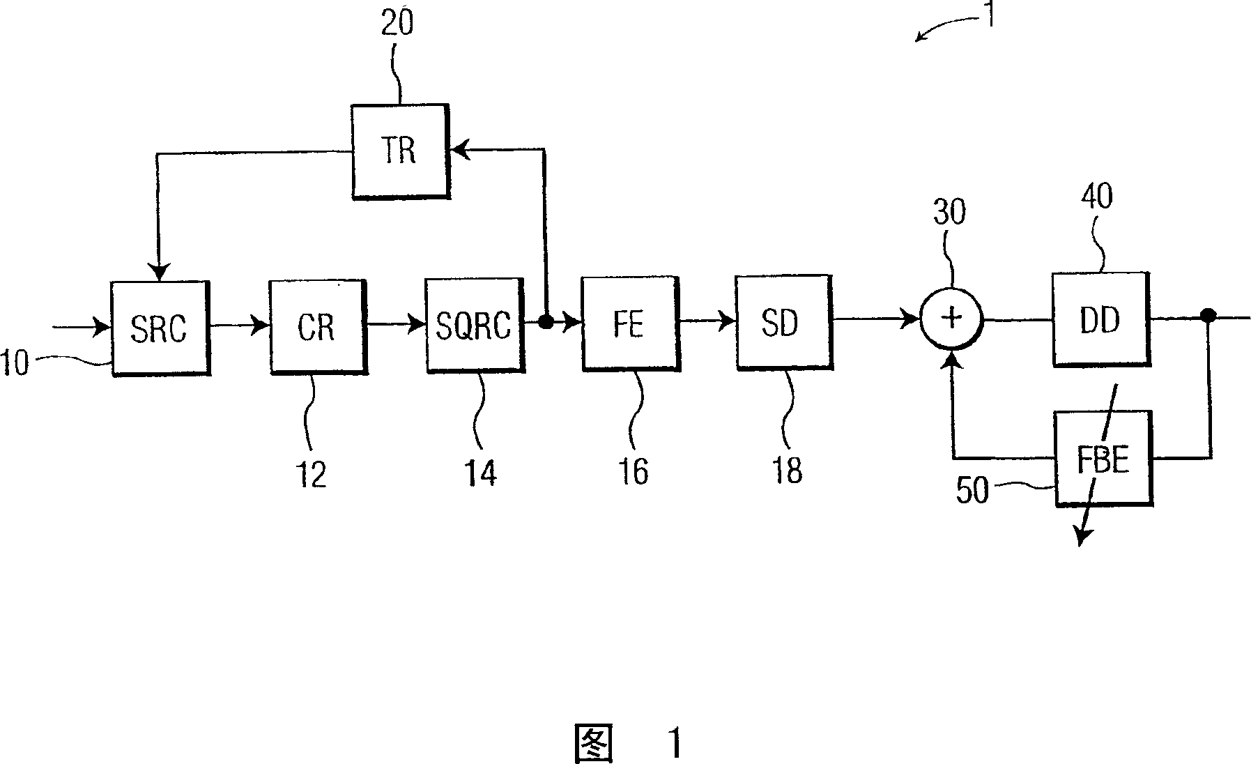
[0023] The present invention provides a digital television receiver which combines equalization and timing recovery functions. More particularly, a DTV receiver according to the present invention utilizes an equalized signal as input to a timing recovery loop.
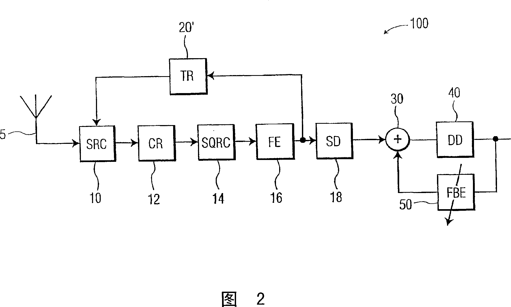
[0024] A preferred embodiment of a DTV receiver 100 according to the invention is shown in connection with an antenna 5 in FIG. 2 . The DTV receiver comprises a sample rate converter (SRC) 10, a carrier recovery (CR) circuit 12, a square root raised cosine (SQRC) filter 14, a forward equalizer (FE) 16, a sync detector ( SD) 18, an arithmetic unit 30 and a decision unit (DD) 40, which are arranged in an arrangement similar to that given in FIG. However, in FIG. 2, timing recovery (TR) circuit 20' receives the output of FE16 and generates a TR control signal which is applied to the control input of SRC10. Note also that the output of DD 40 is applied to feedback equalizer 50, and the output of the feedback equalizer is a...
PUM
 Abstract
Description
Claims
Application Information
 - R&D Engineer
- R&D Manager
- IP Professional
- Industry Leading Data Capabilities
- Powerful AI technology
- Patent DNA Extraction
Browse by: Latest US Patents, China's latest patents, Technical Efficacy Thesaurus, Application Domain, Technology Topic, Popular Technical Reports.
© 2024 PatSnap. All rights reserved.Legal|Privacy policy|Modern Slavery Act Transparency Statement|Sitemap|About US| Contact US: help@patsnap.com