
Directly-down backlight module

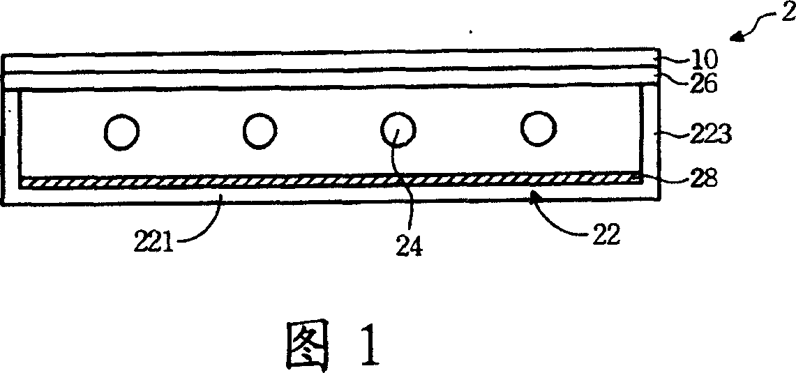
A backlight module and direct-type technology, applied in the field of support columns of direct-type backlight modules, can solve problems such as insufficient support capacity, stability, and failure of the support capacity of support columns 4, and achieve stable support capacity, average brightness, and simplified assembly The effect of steps

Active Publication Date: 2007-05-02
AU OPTRONICS CORP
View PDF4 Cites 0 Cited by
  • Summary
  • Abstract
  • Description
  • Claims
  • Application Information

AI Technical Summary

Problems solved by technology

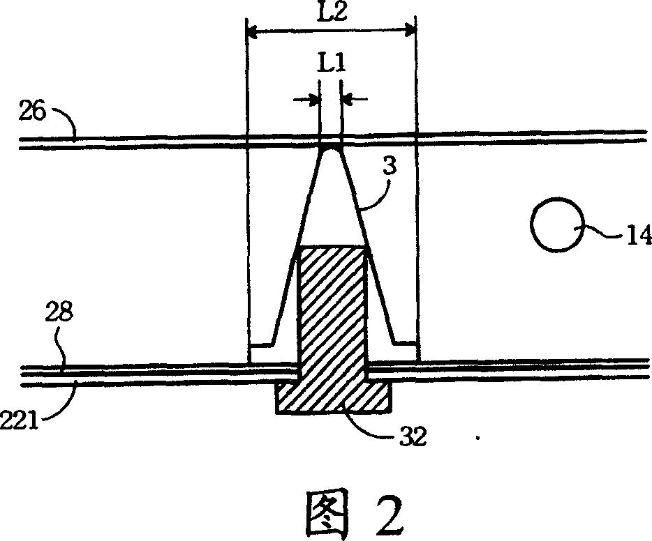
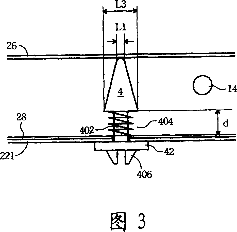
However, since the support column 4 in Fig. 3 is fixed using the spring coil 404, when the spring coil 404 is stressed, the support column 4 can still slide within the range of a length d, and its supporting capacity is obviously not as good as that of the support column in Fig. 2 3 solid
In addition, when the elasticity of the spring coil 404 is exhausted, the supporting capacity of the support column 4 is more likely to fail

Method used


Image

  • Directly-down backlight module
  • Directly-down backlight module
  • Directly-down backlight module

Examples


Embodiment Construction

[0048] Please refer to FIG. 4A . FIG. 4A is a side sectional view of the supporting unit of the present invention installed in a backlight module. The backlight module 5 at least includes a bottom plate 51 , a reflection sheet 52 , a light source 53 , a diffusion plate 54 and a support unit 55 of the present invention. Wherein the base plate 51 is located below the light source 53, the diffusion plate 54 is located above the light source 53, the reflection sheet 52 is laid on the upper surface of the base plate 51, and the supporting unit 55 is fixed in the base plate 51 to support the diffusion plate 54 upwards, and at least A fixing hole 511 and at least one fastening hole 512 are used for fixing the supporting unit 55 .

[0049] As shown in FIG. 4A , the support unit 55 includes a flat plate 551 , a column 552 , a locking bolt 553 , and a fixing buckle 554 . The flat plate 551 is arranged parallel to the bottom plate 51 . The cylinder 552 protrudes from the upper surface ...


PUM


Abstract

The invention discloses a straight-down type backlight module, which is arranged between the bottom plate and dispersion plate of the backlight module for supporting the dispersion plate upward, the bottom plate is provided with a fixed hole and a fastening hole so as to secure the support unit which includes a flat plate, a column, a fastening bolt and a securing clasp, wherein the flat plate is arranged longitudinally to the bottom plate.

Description

technical field [0001] The invention relates to a direct-type backlight module in liquid crystal display technology, in particular to a support column of the direct-type backlight module. Background technique [0002] Liquid crystal display (LCD) technology has been used in portable electronic products such as notebook computers, mobile phones, digital cameras, camcorders, and PDAs. In addition to these smaller portable products, the manufacturing technology of large-size liquid crystal panels has also matured recently. For example, desktop LCD monitors are gradually replacing CRT screens. LCD TVs are currently competing with traditional TVs in the market due to their advantages of light and small size. The liquid crystal panel (LCD panel) is the most critical display element in this field. However, it does not emit light by itself and requires a backlight source to display. Currently, there are many backlight technologies, and in large-size (about 2 inches or more) liqui...

Claims


Application Information

Patent Timeline
Patent Type & Authority Patents(China)
IPC IPC(8): G02F1/1335G02B5/02
Inventor 赖冠州
Owner AU OPTRONICS CORP
Learn More