Steel concrete assembled beam by asymmetric section steel beam

A concrete and asymmetric technology, applied in the field of composite beams, can solve the problems of prolonging the construction period and increasing the construction cost.

Inactive Publication Date: 2007-05-02
DAEWOO ENG & CONSTR CO LTD +3
View PDF4 Cites 2 Cited by
  • Summary
  • Abstract
  • Description
  • Claims
  • Application Information

AI Technical Summary

Problems solved by technology

Since the installation of these stirrups 3 requires separate stiffeners, which prolongs the construction period and increases construction costs, these are other issues that need to be considered

Method used


Image

  • Steel concrete assembled beam by asymmetric section steel beam
  • Steel concrete assembled beam by asymmetric section steel beam
  • Steel concrete assembled beam by asymmetric section steel beam

Examples


Embodiment Construction

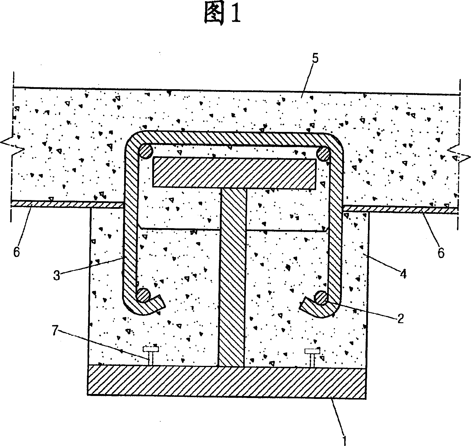
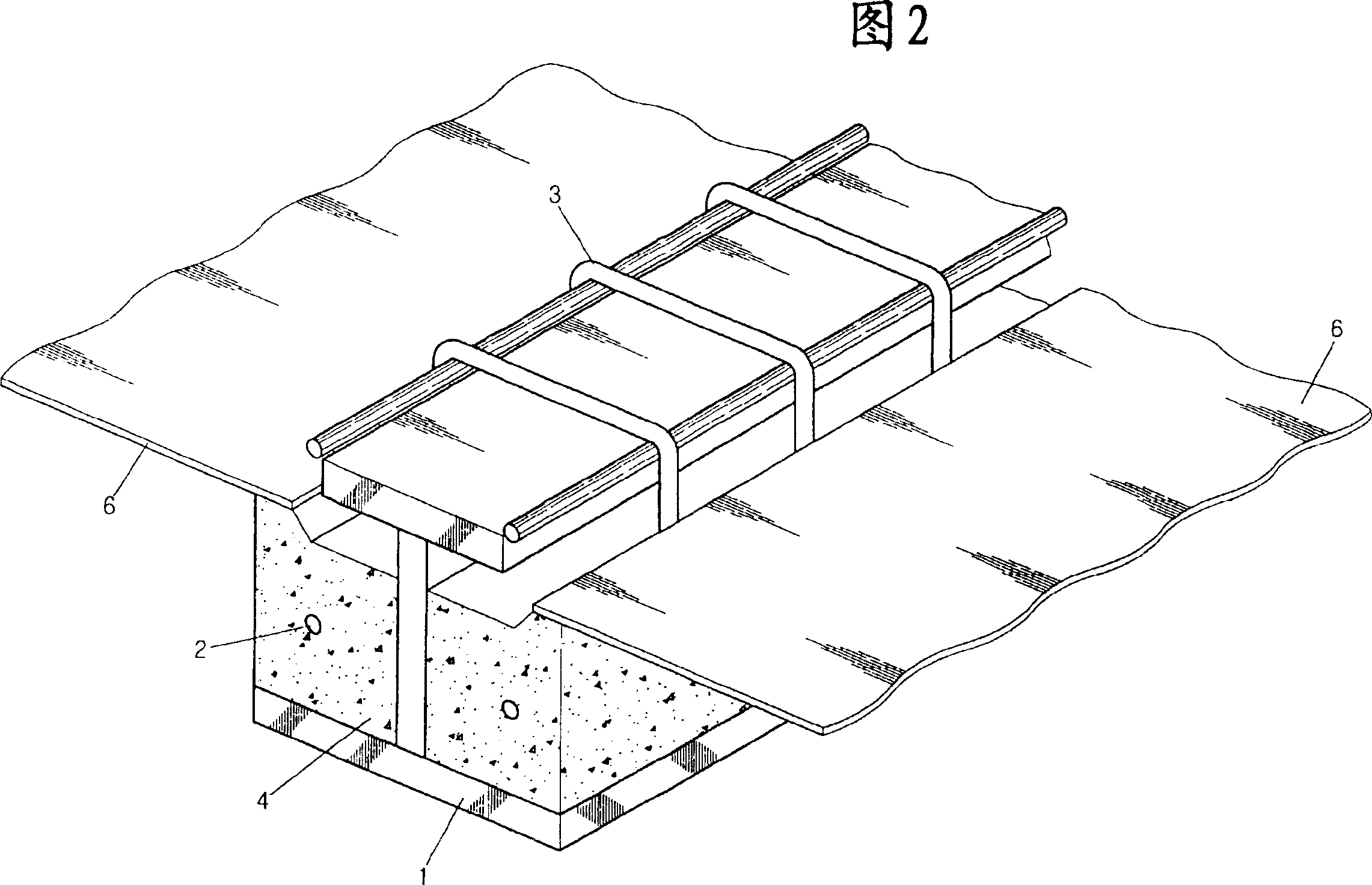
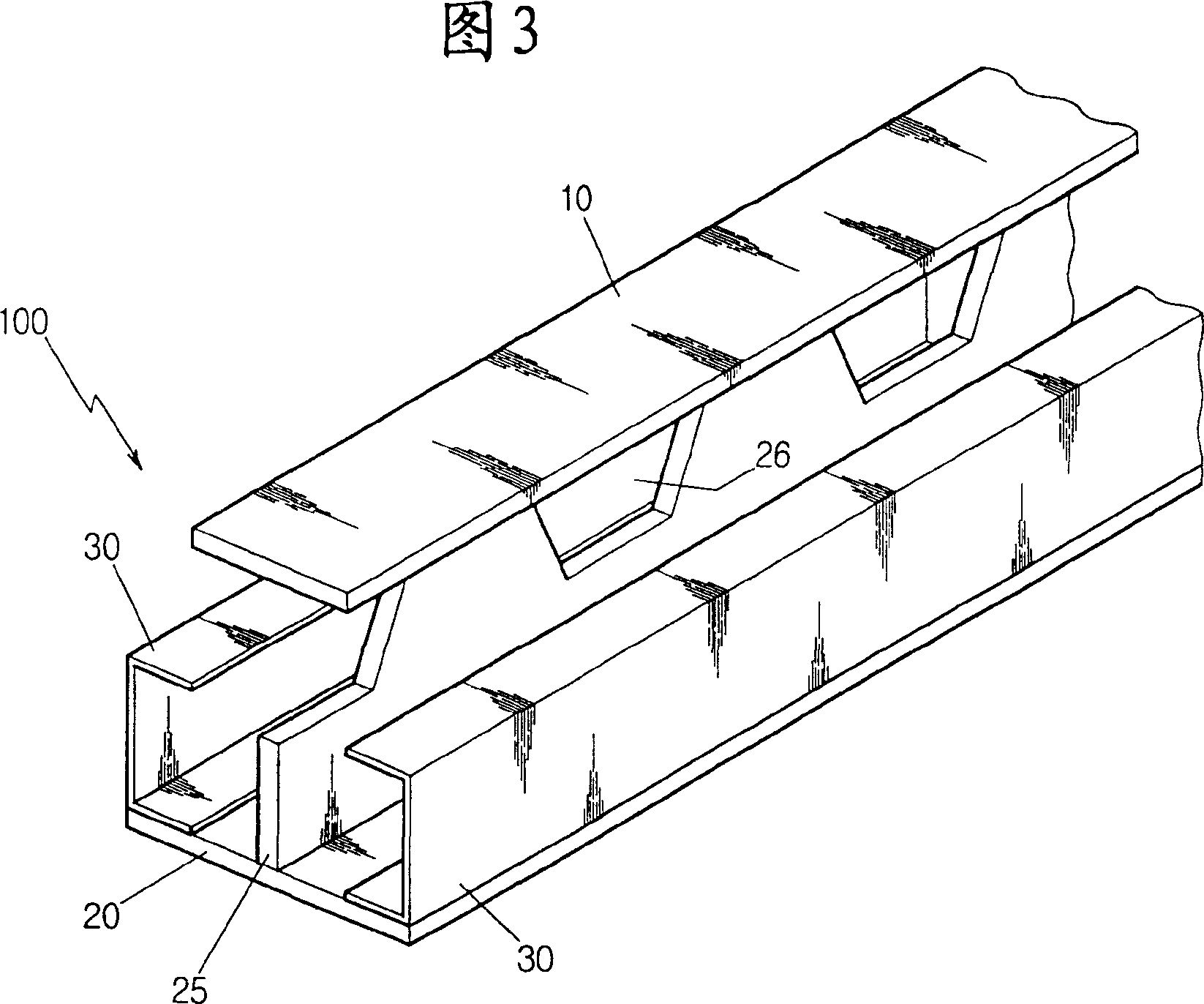
[0021] DETAILED DESCRIPTION OF THE PREFERRED EMBODIMENTS Preferred embodiments of the present invention will be described below with reference to the accompanying drawings.

[0022] Fig. 3 is a perspective view of an asymmetric section steel beam used in the steel-concrete composite beam of the present invention. Figure 4 is a perspective view of an asymmetrical section steel beam provided with a metal cover plate prior to formation of the upper concrete slab.

[0023] As shown in Fig. 3, the asymmetric section steel girder 100 used in the steel-concrete composite beam of the present invention includes: an asymmetric I-beam with an upper flange 10, a web 25 and a lower flange 20; And a pair of C-section steel 30 connected to the lower flange 20 of the asymmetric I-beam. The asymmetric I-steel mentioned here refers to an I-steel with an asymmetric cross section, the width of the upper flange 10 is smaller than the width of the lower flange 20 . At least one opening 26 at a pr...


PUM


Abstract

A concrete steel composite beam is formed by: an asymmetric H sectional steel, which has some notches, at least one, spaced at certain distance on its web, a pair of C sectional steels connected with the lower side of the said H sectional steel to form a space to fill concrete in, a cover plate supported by the tops of the C sectional steels with one, at least, lateral reinforcing rib through the said notches vertically, and another cover plate to form a concrete board with preset thickness by filling concrete to bury the top side of the H sectional steel.

Description

field of invention [0001] The present invention relates to a composite beam made by combining steel beam and concrete, in particular to a steel-concrete composite beam made by combining an asymmetric I-beam with reinforced concrete, wherein the asymmetric I-beam The beam is designed such that the upper flange is narrower than the lower flange. Background technique [0002] Composite beams are generally integrally formed by a shear connection between a steel beam and a reinforced concrete slab. The bending stiffness of this composite beam is about 2 to 3 times greater than that of steel beams. As a result, composite beams experience less deformation due to applied loads, which is particularly beneficial for beams subjected to vibration or shock loads. [0003] In addition, compared with reinforced concrete beams, the self-weight of composite beams can be reduced by 20 to 30%, so it is also conducive to the lightweight of buildings. Due to these advantages, composite beams ...

Claims


Application Information

Patent Timeline
IPC IPC(8): E04B1/30
Inventor 金大英朱英奎千圣哲金相大郑光良李灿炯金道铉文日燮
Owner DAEWOO ENG & CONSTR CO LTD
Why Eureka
Try Eureka