
A method of service backup in asynchronous transmission mode group network

A technology of asynchronous transfer mode and business backup, which is applied in the field of business backup in the asynchronous transfer mode equipment network, and can solve the problems of inflexible networking and high cost

Inactive Publication Date: 2007-03-21
HUAWEI TECH CO LTD
View PDF4 Cites 0 Cited by
  • Summary
  • Abstract
  • Description
  • Claims
  • Application Information

AI Technical Summary

Problems solved by technology

Since this requires an additional set of transmission equipment, it is expensive and the networking is not flexible

Method used


Image

  • A method of service backup in asynchronous transmission mode group network
  • A method of service backup in asynchronous transmission mode group network
  • A method of service backup in asynchronous transmission mode group network

Examples


no. 1 example

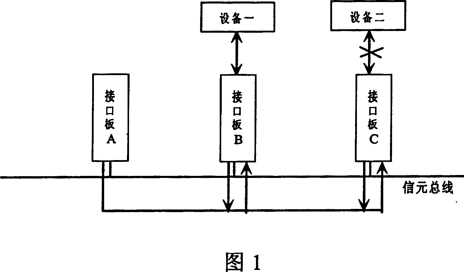
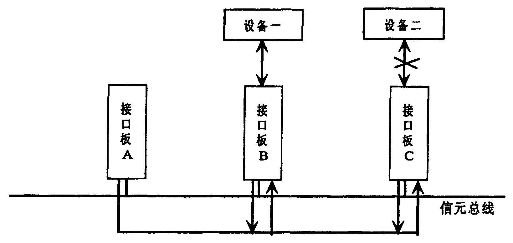
[0045] In the ATM equipment at the access layer, the bus-type switching structure shown in Figure 1 is generally used for connection. For the sake of simplicity, here it is assumed that the three interface boards A, B, and C realize the exchange of ATM cells based on the bus-type switching structure. Interface board B and interface board C provide uplink interfaces and are connected to device 1 and device 2 respectively, that is, they are connected to the upper-layer network through two uplink interfaces.

[0046] In order to ensure that the services accessed through interface board A are stably and reliably transmitted to the upper-layer network (that is, devices 1 and 2) through the two uplink interfaces on interface board B and interface board C, it is necessary to provide the services between these two interfaces. Choose a path. The specific implementation method is as follows:

[0047] When establishing a permanent virtual connection, in the direction from interface boar...

no. 2 example

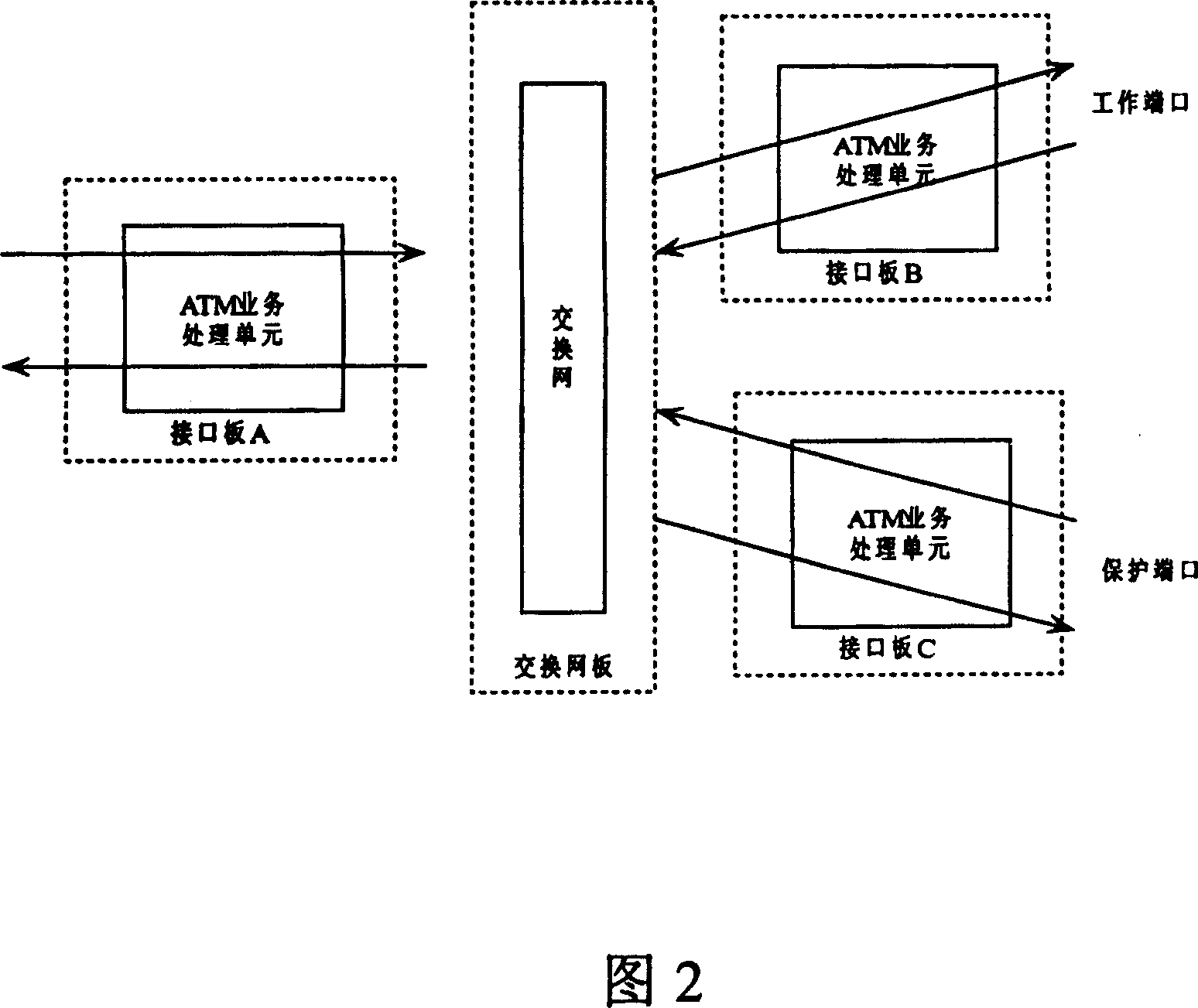
[0053] In the backbone layer and aggregation layer equipment, due to the high demand for switching capacity, the centralized switching structure shown in Figure 2 is generally used for connection. C and the switching network board are connected to the switching network to realize the switching of ATM cells, and interface boards B and C provide working ports and protection ports respectively.

[0054] In order to ensure that the services accessed by interface board A are transmitted stably and reliably through the two ports on interface boards B and C, two selection paths need to be provided for the services. The specific implementation method may also adopt the configuration of one multicast connection with two leaves + two unidirectional unicast connections, which will be further described below.

[0055] When establishing a permanent virtual connection, in the direction from interface board A to interface boards B and C, first establish a root node of a multicast connection ...


PUM


Abstract

The invention provides a method on device service backup in asynchronous transfer mode(ATM) group net system, which has excellence about realizing easy but protect function strongly. In the method the invention applied, providing redundant virtual channel internet to realize service backup by configuring multicast connect properly or unilateralism singlecast connect for carry services, at one time, by using physice layer alarming and ATM layer alarming, to realize that the service detect fail fast and switch. Particularly, in order to protect destination terminal of unilateralism virtual connect, it configure source terminal leaf node of multicast virtual channel connect root node. But, in order to protect source node of unilateralism virtual connect, it creates unilateralism singlecast virtual channel connect from each source terminal (including job and including two terminal) to destination terminal, each unilateralism singlecast virtual channel connect has the same virtual path identifier(VPI) / virtual channel identifier(VCI) and flow parameter, and configure one of the unilateralism singlecast virtual channel connect with the state of the active, the other unilateralism singlecast virtual channel connect with the state of the non-active as reservation connect.

Description

technical field [0001] The invention relates to a service backup method in an asynchronous transfer mode (ATM) equipment network, in particular to a method for realizing service backup and quickly detecting service channel failures by utilizing the ATM multicast function. Background technique [0002] Asynchronous Transfer Mode (ATM) is a fast packet-switching technology that uses fixed-length packets of data called cells. ATM cells only need bandwidth when there is data transmission, but can provide time slots equivalent to time division multiplexers for continuous transmission. Each ATM connection is identified by a label in the header of the letter. The label includes a virtual channel identifier (Virtual Channel Identifier, hereinafter referred to as VCI) and a virtual path identifier (Virtual Path Identifier, hereinafter referred to as VPI) VPI. A virtual channel (Virtual Channel, hereinafter referred to as VC) is a communication path for transmitting ATM cells betwee...

Claims


Application Information

Patent Timeline
IPC IPC(8): H04L12/42H04L12/26H04B1/74H04L12/28H04L12/54H04L12/70H04Q3/00
CPCH04L2012/5627H04L12/5601
Inventor 柯善风李科万席锋
Owner HUAWEI TECH CO LTD
Learn More