Radiating device used in optical memory/reading apparatus

An optical storage and reading device technology, applied in the direction of reducing the physical parameters of the carrier, can solve the problems of poor data reading effect and component failure.

Inactive Publication Date: 2007-02-28
LITE ON IT
View PDF1 Cites 0 Cited by
  • Summary
  • Abstract
  • Description
  • Claims
  • Application Information

AI Technical Summary

Problems solved by technology

[0005] However, the read-write head 4 of the optical disc player 2 and the chip 10 on the circuit board 6 will emit high heat when the optical disc player 2 operates, so that the effect of reading data will be bad, or the optical disc player 2 will be damaged. Component failure in

Method used


Image

  • Radiating device used in optical memory/reading apparatus
  • Radiating device used in optical memory/reading apparatus
  • Radiating device used in optical memory/reading apparatus

Examples


Embodiment Construction

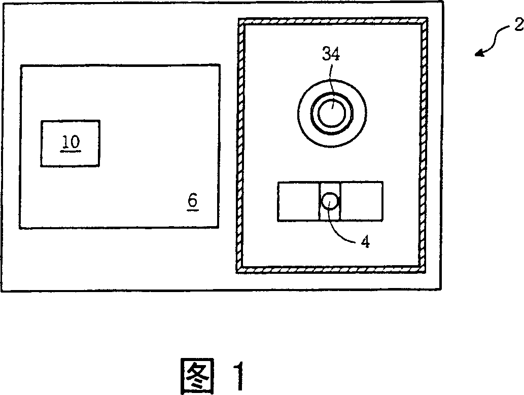
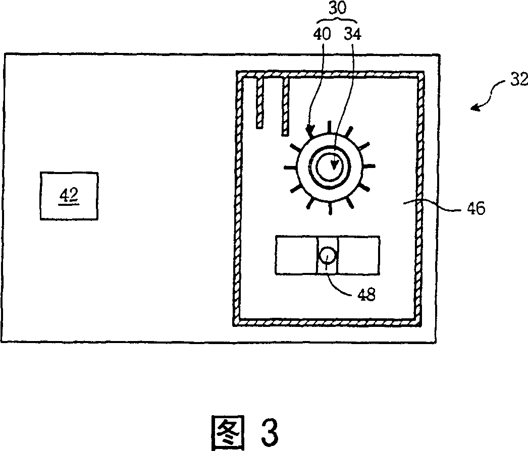
[0043] Please refer to FIG. 3 . FIG. 3 is a schematic diagram of the heat dissipation device 30 and the optical disc player 32 of the present invention. The present invention relates to a heat dissipation device 30 used in an optical storage / reading device, such as an optical storage / reading device of a disc player 32 (VCD player, DVD player), for storing / reading optical discs such as optical discs Store data on media. The CD player 32 also includes heat source components such as the chip 42 and the read / write head 48 as described in FIG. 1 . The heat dissipation device 30 includes not only the clamping mechanism 34 of the known optical disc player 32 , but also a fan blade set 40 .

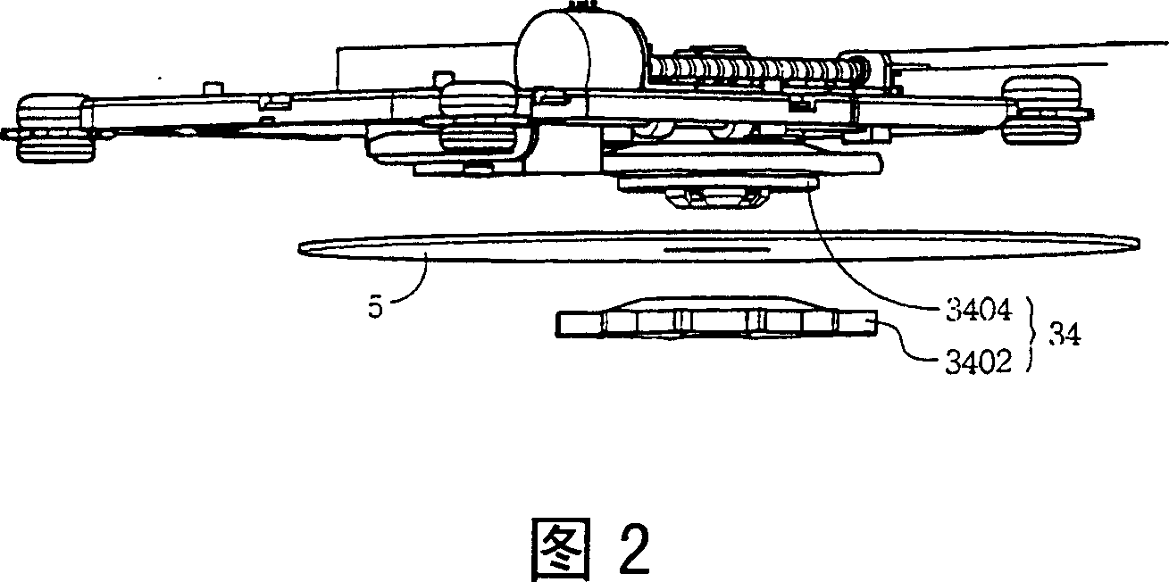
[0044] Referring to FIG. 2 of the prior art, the clamping mechanism 34 is used to clamp the optical storage medium. The clamping mechanism 34 includes a clamper 3402 (clamper) and a spindle motor 3404 (spindle motor). The optical storage medium is clamped by the spindle motor 3404 and the clamp...


PUM


Abstract

A heat radiation device in optical storage / fetch unit used to store / fetch data on optical storage media consists of a holding mechanism for holding and rotating the optical storage media, fan blade set being installed in the holding mechanism and being brought to rotate to generate airstream for achieving heat radiation effect.

Description

technical field [0001] The invention relates to an optical storage / reading device, especially a heat dissipation device used in the optical storage / reading device. Background technique [0002] Please refer to FIG. 1 . FIG. 1 is a schematic diagram of a known optical disc player 2 . An optical storage / reading device such as a CD player (VCD player, DVD player) 2 includes a pickup head 4, a circuit board 6, a holding mechanism 34... and other components. [0003] The read / write head 4 is used to read the data on the surface of the optical storage medium (not shown) placed in the optical disc player 2, and the common optical storage medium is an optical disc. The read data needs to be calculated and processed by the chip 10 on the circuit board 6, so that the subsequent CD player 2 can play the processed data in the form of video / audio multimedia. [0004] Please refer to FIG. 2 . FIG. 2 is a schematic diagram of a clamping mechanism 34 in the known technology. The clamping...

Claims


Application Information

Patent Timeline
Patent Type & Authority Patents(China)
IPC IPC(8): G11B33/14
Inventor 张龙国
Owner LITE ON IT
Why Eureka
Try Eureka