Inductance coil and divider applied for speaker
A technology of inductance coils and coils, applied in the direction of inductors, fixed inductors, sensors, etc., can solve the problems of hard high pitch, gray hearing, gray voice, etc., to achieve the effect of clear sound and high intelligibility of speech
- Summary
- Abstract
- Description
- Claims
- Application Information
AI Technical Summary
Problems solved by technology
Method used
Image

Examples
Embodiment 1
[0021] Embodiment 1, an induction coil 1 .
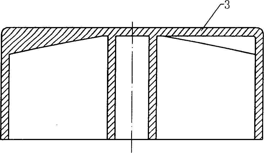
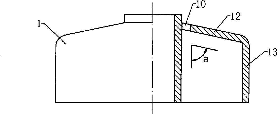
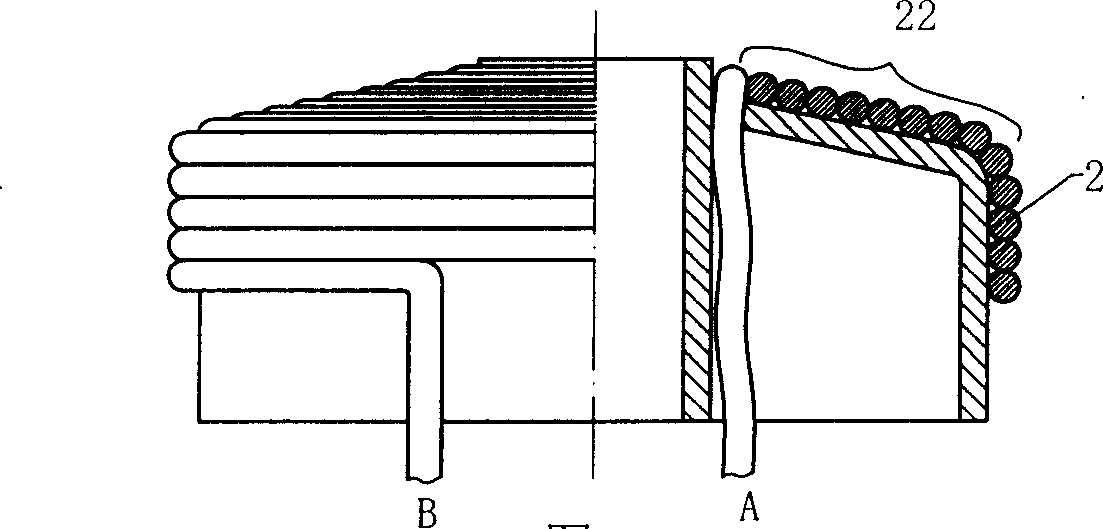
[0022] refer to figure 1 , The inductance coil is composed of a core body 1, an enameled wire 2 wound on the surface of the core body and a cover 3. The core body 1 includes two parts: a platform section 12 and a cylinder body 13. The angle a between the slope and the axis of the core body is about 80°. The core body is processed by plastic injection molding and has a hollow structure. First insert the enameled wire 2 into the lead hole 10, the end of which is the lead wire A, and then wind it to the cylinder section 13 in a single layer on the surface of the core body, and the end of the enameled wire is the lead wire B to form the inductance coil L1. in, Picture 1-1 is a schematic diagram of the structure of the cover, Figure 1-2 is a schematic diagram of the structure of the core, Figure 1-3 It is a schematic diagram of the enameled coil winding process, figure 1 It is the schematic diagram of the structure of the inducta...
Embodiment 2
[0023] Embodiment 2, inductance coil 2.
[0024] refer to figure 2 , The inductance coil is composed of a core 1, an enameled wire 2 wound around the core and a cover 3. The core body contains a radial groove 11, and the enameled wire 2 is wound from the bottom of the groove to the core body cylinder 13 to form an inductance coil. The core body is processed by plastic injection molding and has a hollow structure. First insert the enameled wire 2 into the lead hole 10, the end of which is the lead A, and then start winding to the cylinder 13 according to the bottom of the radial groove 11 of the core body, and the end of the enameled wire is the lead B to form the inductance coil L1. in, diagram 2-1 is a schematic diagram of the structure of the cover, Figure 2-2 is a schematic diagram of the structure of the core, Figure 2-3 It is a schematic diagram of the enameled coil winding process, figure 2 It is the schematic diagram of the structure of the inductance coil L1....
Embodiment 3
[0025] Embodiment 3, inductance coil 3.
[0026] refer to image 3 , The inductance coil, compared with embodiment 2, differs in the groove. The grooves in Example 2 are radial grooves, while the grooves in this example are ordinary grooves, that is, the grooves are not perpendicular to the axis of the core. The rest are correspondingly similar to those in Embodiment 2, and will not be described repeatedly. Figure 3-1 is a schematic diagram of the structure of the cover, Figure 3-2 is a schematic diagram of the structure of the core, Figure 3-3 It is a schematic diagram of the enameled coil winding process, image 3 It is the schematic diagram of the structure of the inductance coil L1.
PUM
 Abstract
Description
Claims
Application Information
 - R&D
- Intellectual Property
- Life Sciences
- Materials
- Tech Scout
- Unparalleled Data Quality
- Higher Quality Content
- 60% Fewer Hallucinations
Browse by: Latest US Patents, China's latest patents, Technical Efficacy Thesaurus, Application Domain, Technology Topic, Popular Technical Reports.
© 2025 PatSnap. All rights reserved.Legal|Privacy policy|Modern Slavery Act Transparency Statement|Sitemap|About US| Contact US: help@patsnap.com