Columnar linear motor in permanent magnet reluctance type
A linear motor, cylindrical technology, applied in the direction of electrical components, electromechanical devices, electric components, etc., can solve the problems of uneven axial distribution of the excitation magnetic field, low performance-to-volume ratio of the motor, and achieve improved performance-to-volume ratio and performance-to-weight ratio Ratio, uniform distribution, and longer core length
- Summary
- Abstract
- Description
- Claims
- Application Information
AI Technical Summary
Problems solved by technology
Method used
Image
Examples
specific Embodiment approach 1
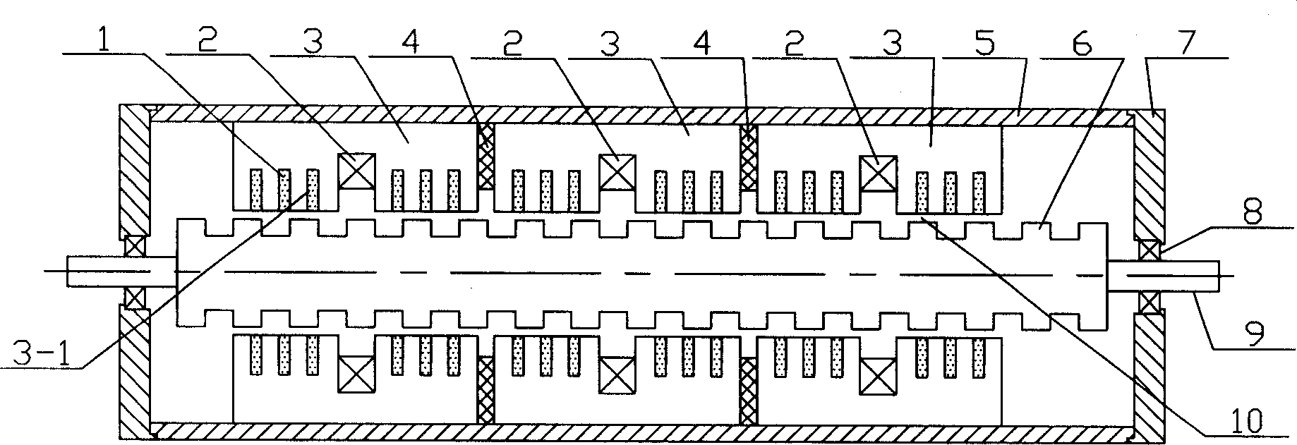
[0011] Specific implementation mode one: see figure 1 , This embodiment consists of a permanent magnet 1, an armature winding 2, an armature core 3, a magnetic isolation ring 4, a casing 5, a non-armature core 6, an end cover 7, a bearing 8 and a shaft 9. The two end caps 7 are respectively connected to both ends of the casing 5, the outer rings of the two bearings 8 are respectively fixed in the inner holes of the two end caps 7, and the inner rings of the bearings 8 are fixedly connected to the shaft 9 . This motor is the movable structure of the non-armature iron core 6, the non-armature iron core 6 is cylindrical and is sleeved on the said shaft 9, the said armature iron core 3 is cylindrical, and the said armature iron core 3 The outer circular surface of the said casing 5 closely fits, an air gap 10 is formed between said armature core 3 and said non-armature core 6, said armature core 3 and said non-armature core 6. On the surface facing the air gap 10, ring-shaped s...
specific Embodiment approach 2
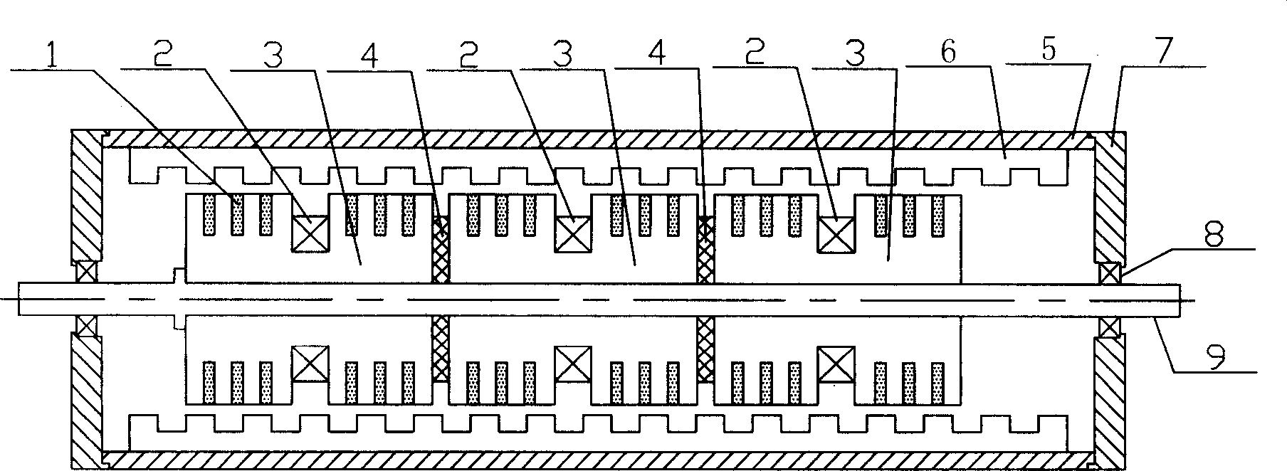
[0012] Specific implementation mode two: refer to figure 2 , the present embodiment is composed of the casing 5, the shaft 9 arranged on the central axis of the casing, the armature core 3, the magnetic isolation ring 4 arranged between the armature cores 3 of each phase, and arranged in each phase. Said armature core 3 is composed of annular armature winding 2 and non-armature core 6 between the two poles. The non-armature core 6 is cylindrical, and said armature core 3 is cylindrical. An air gap 10 is formed between the armature core 3 and the non-armature core 6, and the surfaces of the armature core 3 and the non-armature core 6 facing the air gap 10 are sequentially provided with annular rings along the axial direction. The tooth slot, the motor is the movable structure of the armature core 3, the armature core 3 is sleeved on the shaft 9, the outer circular surface of the non-armature core 6 and the inner surface of the casing 5 Closely fit, an annular permanent magnet...
specific Embodiment approach 3
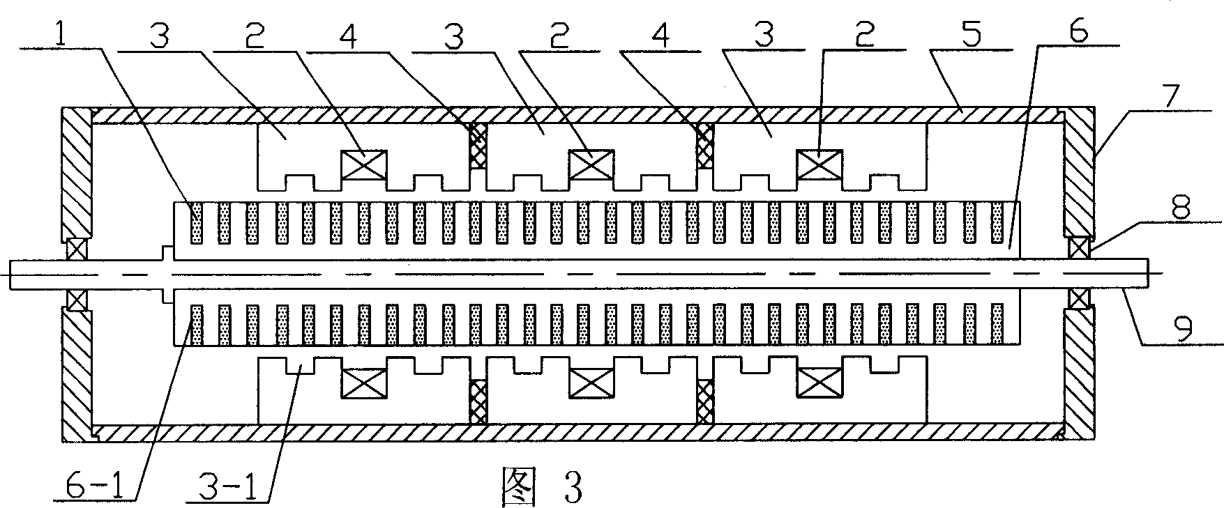
[0013] Specific embodiment three: referring to Fig. 3, present embodiment is made up of casing 5, the axle 9 that is arranged on the central axis place in said casing, armature core 3, is arranged on the spacer between said armature core 3 of each phase. The magnetic ring 4, the annular armature winding 2 arranged on the armature core 3 of each phase and located between the two poles and the non-armature core 6 are composed of a cylindrical non-armature core 6, and the armature The armature core 3 is cylindrical, an air gap 10 is formed between the armature core 3 and the non-armature core 6, and the surfaces of the armature core 3 and the non-armature core 6 face the air gap 10 There are annular tooth grooves sequentially opened along the axial direction. The motor is a movable structure of the non-armature core 6. The non-armature core 6 is sleeved on the shaft 9. The outer circular surface of the armature core 3 Closely fit with the inner surface of the casing 5, the perman...
PUM
 Abstract
Description
Claims
Application Information
 - R&D Engineer
- R&D Manager
- IP Professional
- Industry Leading Data Capabilities
- Powerful AI technology
- Patent DNA Extraction
Browse by: Latest US Patents, China's latest patents, Technical Efficacy Thesaurus, Application Domain, Technology Topic, Popular Technical Reports.
© 2024 PatSnap. All rights reserved.Legal|Privacy policy|Modern Slavery Act Transparency Statement|Sitemap|About US| Contact US: help@patsnap.com


