Camera focus changing lens system

一种透镜系统、变焦距的技术,应用在微变焦距透镜系统领域

Inactive Publication Date: 2006-09-27
HANWHA VISION CO LTD
View PDF0 Cites 0 Cited by
  • Summary
  • Abstract
  • Description
  • Claims
  • Application Information

AI Technical Summary

Problems solved by technology

However, this electronic zoom feature has some limitations in terms of satisfying users who want a clearer image

Method used


Image

  • Camera focus changing lens system
  • Camera focus changing lens system
  • Camera focus changing lens system

Examples


Embodiment Construction

[0033] Preferred embodiments of the present invention will be described in detail below in conjunction with the accompanying drawings.

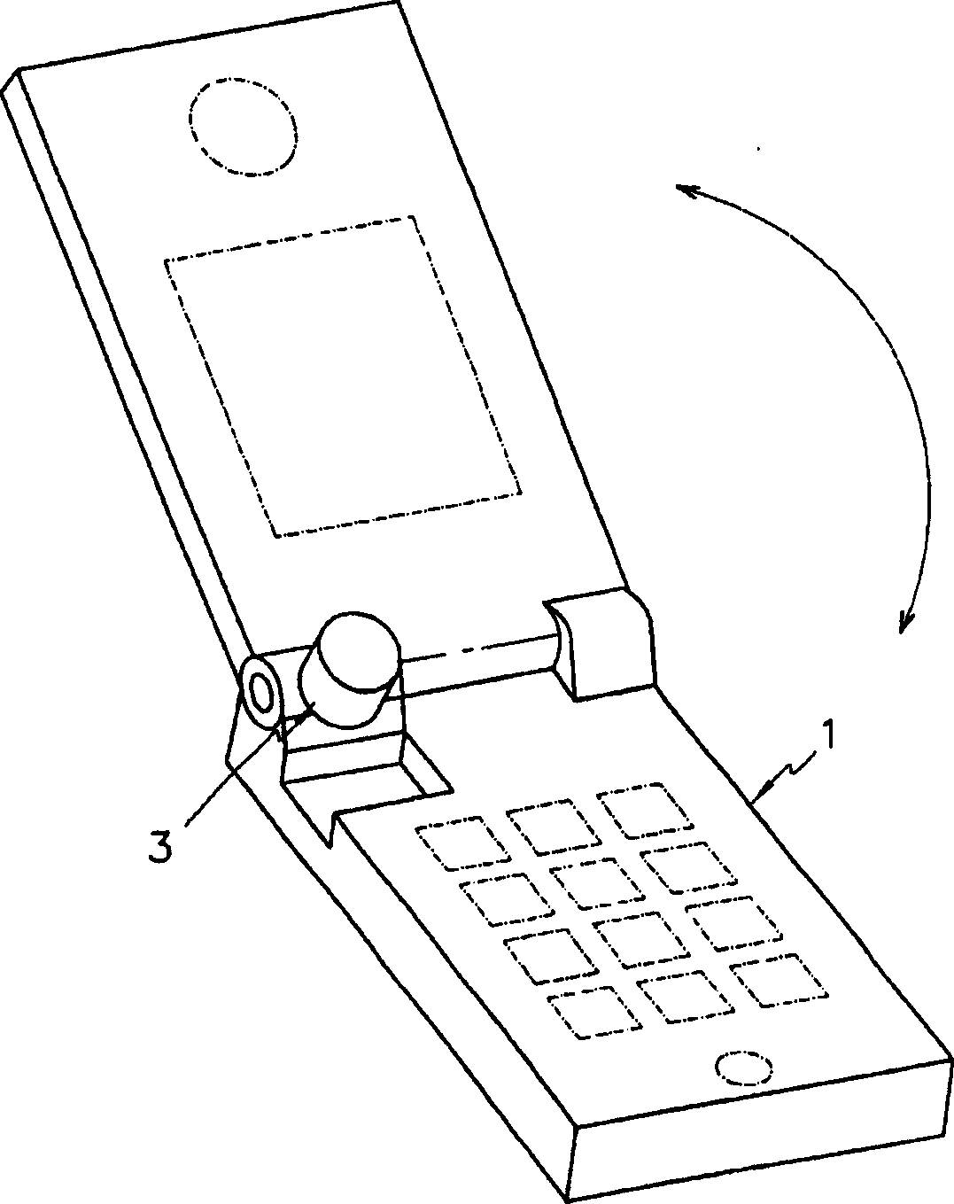
[0034] figure 1 An application example of the varifocal lens system of the present invention is shown, in which the varifocal lens system 3 is applied to a portable electronic device such as a mobile phone 1 .

[0035] The zoom lens system 3 constitutes a micro-scale and is designed to realize a zoom function. That is, the zoom lens system 3 is designed to be accommodated in a portable electronic device having an image pickup device, such as a mobile phone 1, a notebook computer, a PC camera, a PDA (Personal Digital Assistant), or a door phone.

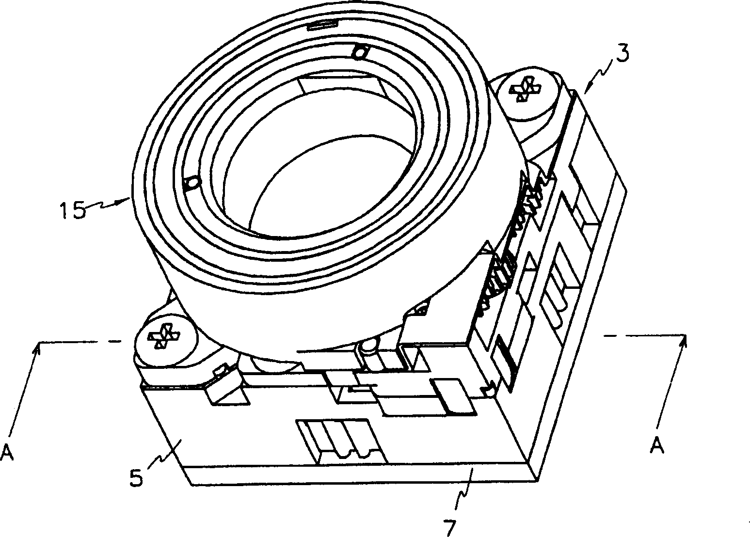
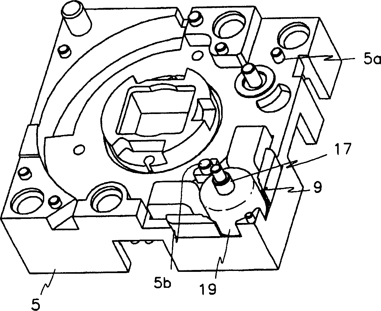
[0036] figure 2 Represents the overall appearance of the zoom lens system of the present invention, image 3 and Figure 4 Indicates the driving source of the zoom lens system, Figure 5 and Figure 6 Indicates the power transmission gear set used to transmit the driving force of the driving s...


PUM


Abstract

A zoom lens system includes a zoom base, a driving source for generating rotational force in accordance with a control signal of a control unit disposed in the electronic facility, plural power transmission gears disposed on the zoom base to reduce the rotational force of the driving source, a first lens cam disposed on the zoom base, plural first lens shafts coupled on the zoom base in a direction of an optical axis and located in the first lens cam, a first lens barrel having a first lens, the first lens barrel being disposed in the first lens cam and slidably coupled to the first lens shaft in the direction of the optical axis, a power transmission member coupled to the first lens cam in the direction of the optical axis, an outer second lens cam disposed on an outer circumference of the first lens cam and fixed on the zoom base, an inner second lens cam disposed in the outer lens cam, plural second lens shafts coupled to the zoom base in the direction of the optical axis and located in the inner second lens cam, and a second lens barrel having a second lens and being disposed in the inner second lens cam.

Description

technical field [0001] The invention relates to a zoom lens system, in particular to a micro zoom lens system, which has an optical zoom function and can be used in a portable communication system. Background technique [0002] Typically, single focus lenses are used as microlens systems in portable communication systems. That is, single-focus lenses of such a simple structure that constitute lenses whose size reaches microscopic order have been widely used. However, since a single focus lens system cannot provide a zoom function, an electronic zoom function processed by software is applied to such a single focus lens system. However, this electronic zoom function has some limitations in satisfying users who want to get a clearer image. Contents of the invention [0003] Therefore, the present invention has made every effort to solve the above-mentioned problems. [0004] An object of the present invention is to provide a micro-scale zoom lens system for use in portable...

Claims


Application Information

Patent Timeline
Patent Type & Authority Patents(China)
IPC IPC(8): G02B7/10G02B15/00
CPCG02B7/10G02B15/00
Inventor 徐在庆
Owner HANWHA VISION CO LTD
Why Eureka
Try Eureka