Installation arrangement for controlling handle operation in a door lock and a door lock provided with an installation arrangement of this kind

A technology for installing structures and operating devices, applied in building locks, connecting components, building construction, etc.

Inactive Publication Date: 2006-07-05
ABLOY OY
View PDF0 Cites 0 Cited by
  • Summary
  • Abstract
  • Description
  • Claims
  • Application Information

AI Technical Summary

Problems solved by technology

Alternatively, when the solenoid is de-energized, the solution may be reversed so that the mounting structure allows correct passage using the handle

Method used


Image

  • Installation arrangement for controlling handle operation in a door lock and a door lock provided with an installation arrangement of this kind
  • Installation arrangement for controlling handle operation in a door lock and a door lock provided with an installation arrangement of this kind
  • Installation arrangement for controlling handle operation in a door lock and a door lock provided with an installation arrangement of this kind

Examples


Embodiment Construction

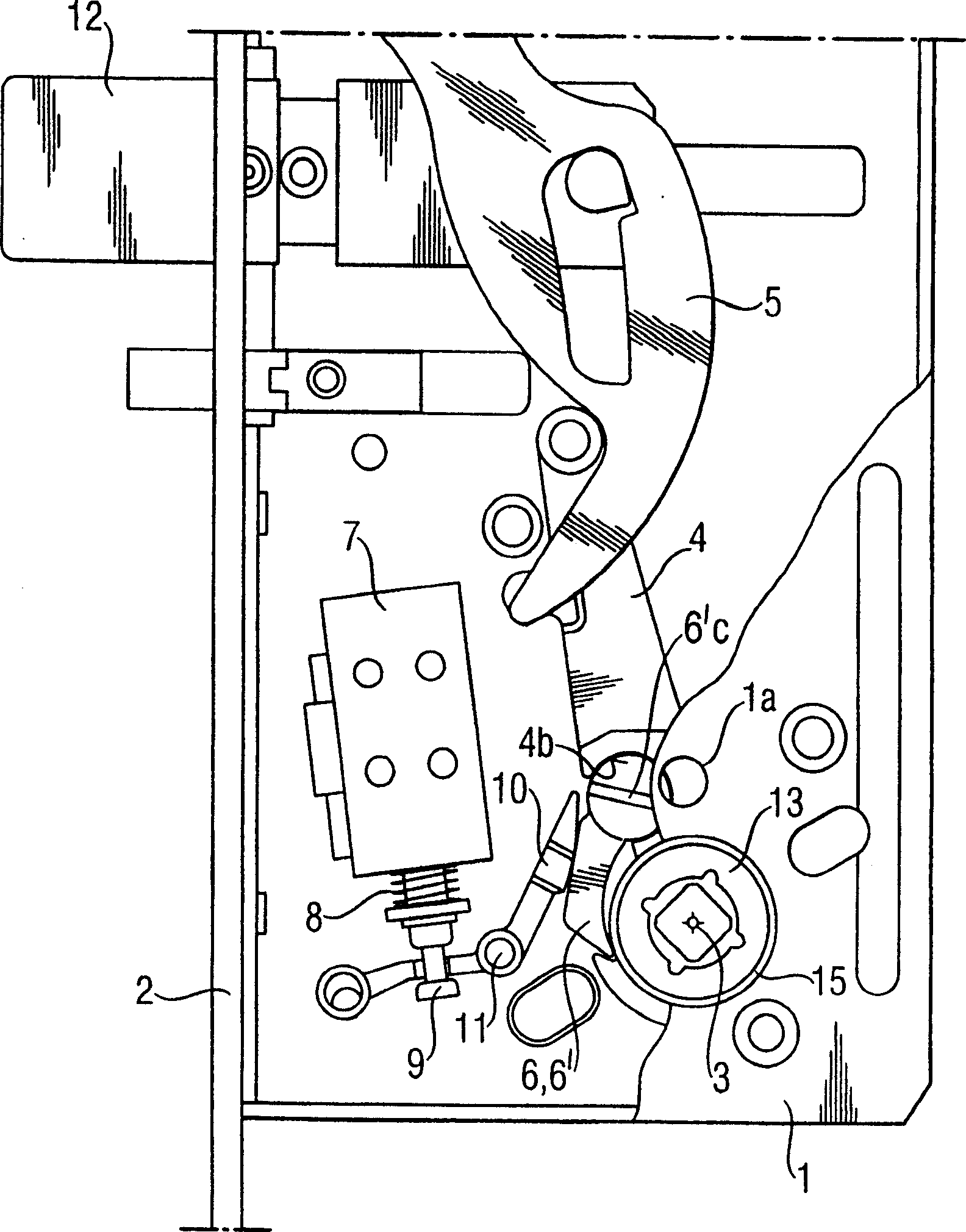
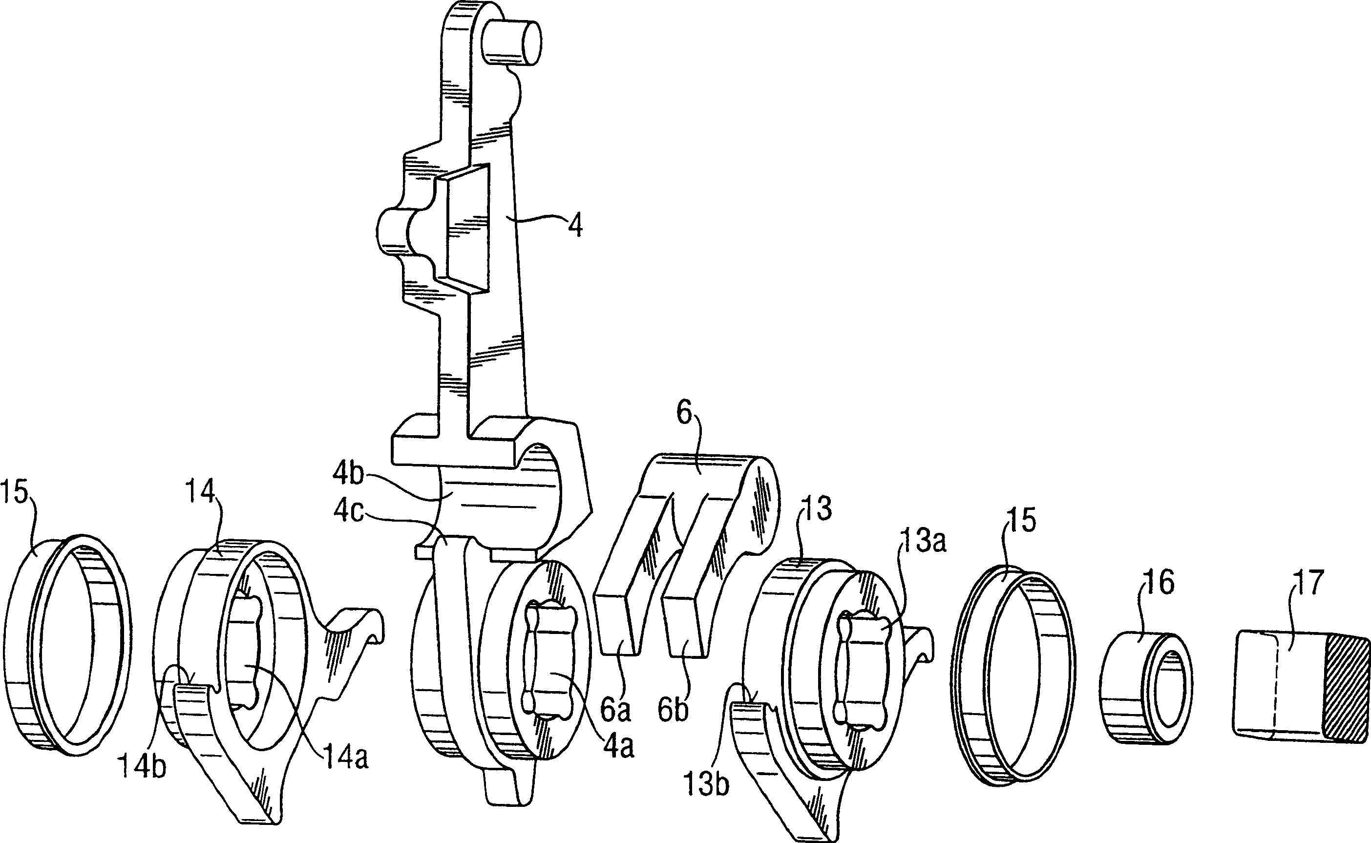
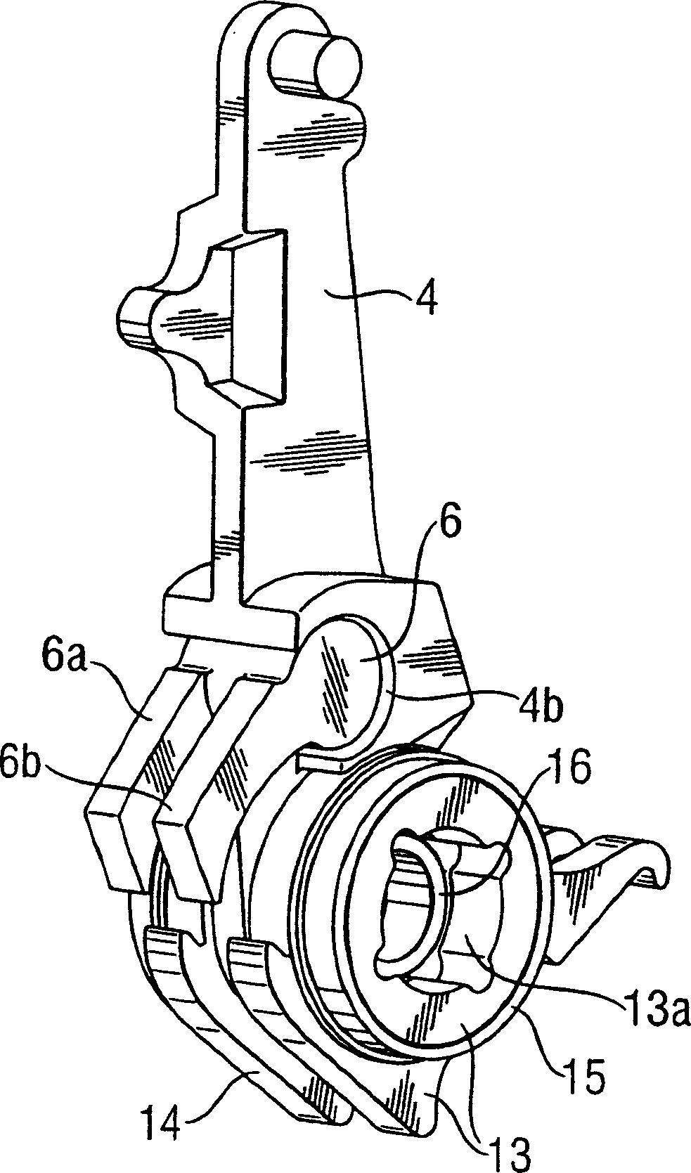
[0024] In the figures, numeral 1 designates a lock box of a door lock having a cover which is shown partially broken away in the figures. The lock box 1 is provided with a front plate 2 through which the deadbolt 12 of the lock is movable. Furthermore, the lock box 1 is provided with an operating axis 3 on which is mounted a follower 4 rotatably supported on the lock box, which in this embodiment is shown by means of an independent force transmission The lever 5 acts on the latch. Depending on the form of the lock, the follower may naturally be arranged to also directly move the deadbolt of the lock when required.

[0025] The follower 4 can actually be influenced from both sides of the lock box. A key or the like for operating the lock mechanism provided with a twist arm or a corresponding force transmission element (not shown) acting directly on the follower 4 is mounted on the operating axis 3 in the lock box as known. side. Alternatively, it is also possible to install...


PUM


Abstract

An installation arrangement for a solenoid controlled handle operation in a door lock in which force transmission from an operation axis (3) for a handle or the like to a follower (4) acting on a bolt (12) of the lock is arranged by means of a movable coupling member (6,6'), which receives its guidance from a solenoid arrangement. The follower (4) is provided with two separate torsion units (13,14) which are installed on the operation axis (3) on different sides of the follower (4) and are turnably supported to it and which can be selectively coupled by means of said coupling member (6,6') to be in force transmission connection with the follower (4).

Description

technical field [0001] The present invention relates to a mounting structure for a solenoid controlled handle operation in a door lock in which the axis of operation of the handle or the like from either side of the door lock to the deadbolt acting on the door lock The force transmission of the follower is arranged by means of a movable joint which is guided by a solenoid arrangement; and relates to a door lock in which the mounting structure described above is used. Background technique [0002] The handle-operated control of the solenoid device in the door lock can be realized in different ways depending on the application. The mounting structure may for example be such that the solenoid allows or enables correct passage with the handle when the solenoid is energized, whereby force transmission from the handle to the deadbolt is engaged. Alternatively, when the solenoid is de-energized, the solution may be reversed so that the mounting structure allows correct passage usi...

Claims


Application Information

Patent Timeline
Patent Type & Authority Patents(China)
IPC IPC(8): E05B47/06E05B59/00
CPCE05B47/0004Y10T70/713Y10T70/5819E05B63/0065E05B47/0688Y10T70/5496Y10T292/0982Y10T70/5416Y10T292/96Y10T292/57
Inventor J·拉尔蒂凯宁
Owner ABLOY OY
Why Eureka
Try Eureka