Clutch assembly

A clutch and assembly technology, applied in the direction of clutches, friction clutches, fluid-driven clutches, etc., can solve the problems of expensive, complex structure of clutch assembly, etc.

Inactive Publication Date: 2006-06-21
SCHAEFFLER TECH AG & CO KG
View PDF6 Cites 4 Cited by
  • Summary
  • Abstract
  • Description
  • Claims
  • Application Information

AI Technical Summary

Problems solved by technology

However, these clutch assemblies are very complex and therefore expensive, and also require a very complex operating system for structural reasons

Method used


Image

  • Clutch assembly
  • Clutch assembly
  • Clutch assembly

Examples


Embodiment Construction

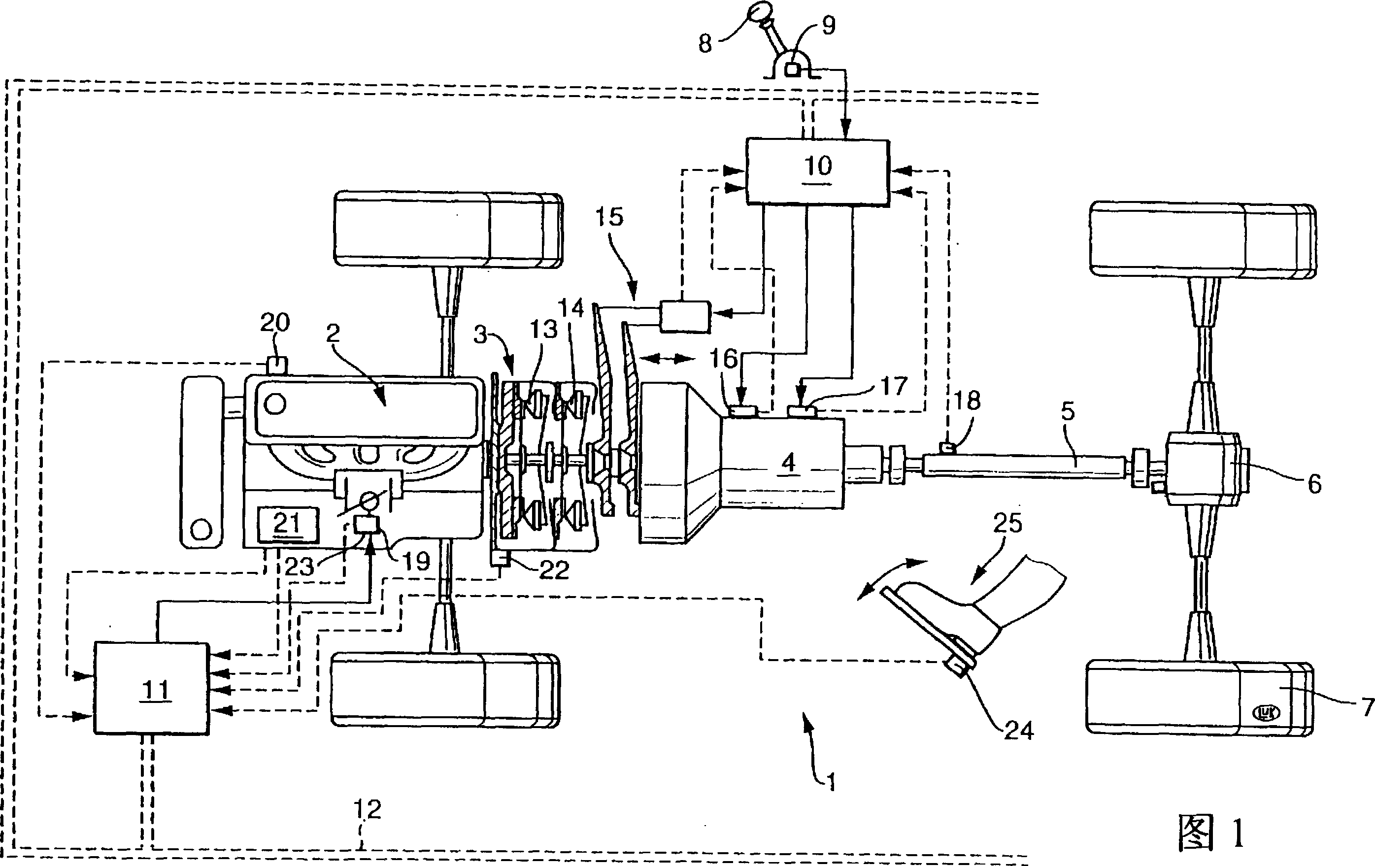
[0023] FIG. 1 shows a motor vehicle 1 with a transmission line comprising an engine 2 consisting of an internal combustion engine, a clutch assembly 3 and a gearbox 4 . Wheels 7 of motor vehicle 1 are driven via a drive shaft 5 and a differential 6 . In this sense, it can of course also be a motor vehicle with one or more other driven axles.

[0024] Also shown here is a gear selection device 8 , such as a selector lever, with a sensor 9 and a control device 10 , 11 in the form of a block diagram. The control devices 10 , 11 can be designed as one unit or in structurally and / or functionally separate subregions. If the control devices 10 , 11 are designed in structurally and / or functionally separate subregions, they can be connected to one another, for example, via a CAN bus 12 or other electrical connections for data exchange. The control devices 10, 11 are used, for example, to automatically operate the gearbox 4 and / or to control the clutches 13, 14 or the engine 2 to whic...


PUM


Abstract

The invention relates to a clutch assembly for transmitting torque between an engine and a gearbox, comprising a torsional vibration damper and at least one clutch unit, characterized in that: in the torsional vibration damper There is an axial plug-in connection with at least one clutch unit, so that the torsional vibration damper can be pre-assembled on the output shaft of the engine and the clutch unit can be pre-assembled on the gearbox side, and The plug connection is brought into an active state when the engine and gearbox are assembled together.

Description

technical field [0001] The present invention relates to a clutch assembly for transmitting torque between an engine and a gearbox. The invention relates in particular to a clutch assembly comprising at least one torsional vibration damper and at least one friction clutch, by means of which the engine and the transmission can be connected and disconnected in a driving manner. Background technique [0002] A clutch assembly with two friction clutches is known, for example, from DE 28 30 659 A1. However, these clutch assemblies are very complex and therefore expensive, and also require a very complex actuating system for structural reasons. Contents of the invention [0003] The object of the present invention is to provide a clutch assembly of the type mentioned at the outset, which has good function and a simple structure and can be manufactured cost-effectively. Furthermore, the clutch unit according to the invention can be actuated in a particularly simple manner, so th...

Claims


Application Information

Patent Timeline
Patent Type & Authority Patents(China)
IPC IPC(8): F16D13/40B60K17/02B62D65/10F16D21/06F16D25/08F16D25/10
CPCF16D21/06F16D2021/0669F16D25/087F16D25/10
Inventor 塞巴斯蒂安·贝内东罗尔夫·迈因哈德
Owner SCHAEFFLER TECH AG & CO KG
Why Eureka
Try Eureka