Capacitance type micromechanical switch

A capacitive micro-mechanical and micro-electronic mechanical technology, which is applied in the direction of circuits, electrical components, waveguide devices, etc., can solve the problems of affecting the switch threshold voltage, large residual stress, and reducing the service life of the switch, so as to achieve long switch life and low Threshold, Buck Threshold Voltage Effects

Inactive Publication Date: 2006-05-24
SOUTHEAST UNIV
View PDF0 Cites 0 Cited by
  • Summary
  • Abstract
  • Description
  • Claims
  • Application Information

AI Technical Summary

Problems solved by technology

[0002] Traditional MEMS capacitive switches generally adopt a fixed-beam structure. The MEMS switch with this structure has the following disadvantages: ① Higher threshold voltage. The threshold voltage of a MEMS capacitive switch with a normal size is about 20~30V; ②It has a large residual stress, and the large residual stress in the elastic beam will not only affect the threshold voltage of the switch, but also reduce the service life of the switch

Method used


Image

  • Capacitance type micromechanical switch
  • Capacitance type micromechanical switch
  • Capacitance type micromechanical switch

Examples


Embodiment Construction

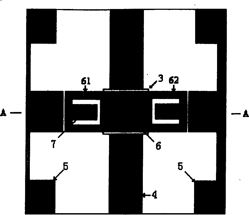
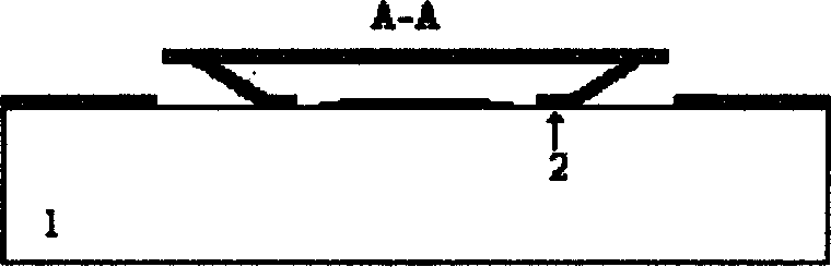
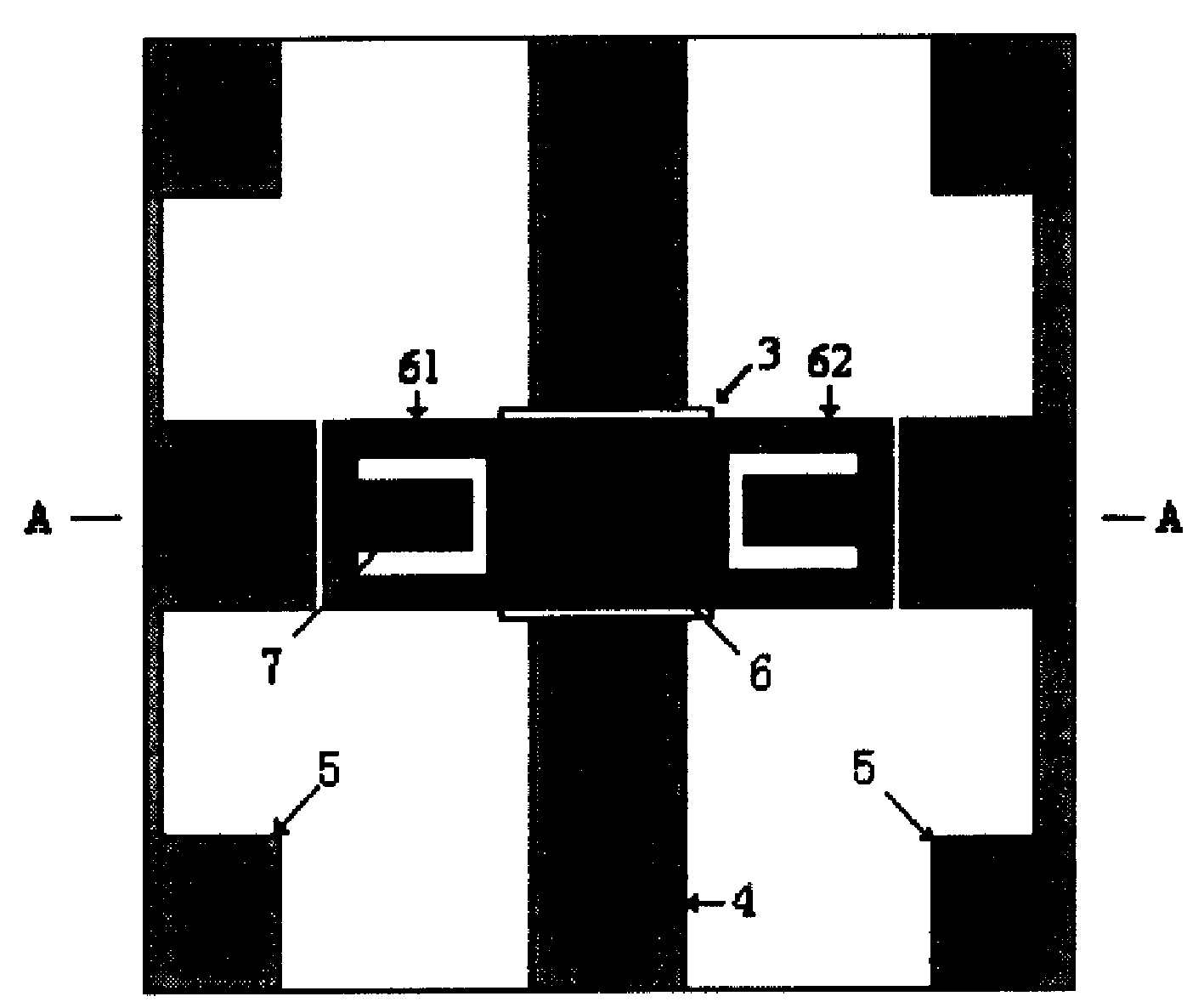
[0008] A capacitive micromechanical switch used in a microelectromechanical system, comprising: a semiconductor substrate 1, on which a bridge pier 2, a coplanar waveguide signal line 4, a ground plane 5 and a flat film beam 6 are arranged. The coplanar waveguide signal line 4 below the flat membrane beam 6 is provided with an insulating dielectric layer 3, and concave notches 61 and 62 are provided at both ends of the flat membrane beam 6, and the bridge pier 2 connects with the flat membrane beam 7 through a "T" shape. The notch ends of the beams 6 are connected. When a DC control voltage is applied, the flat membrane beam deflects under the action of electrostatic force. When the DC voltage increases to a certain value, the flat-membrane beam is in contact with the insulating layer. At this time, a large coupling capacitance is formed between the flat-membrane beam and the coplanar waveguide signal line, the signal is reflected, and the switch changes from "on" For "off" s...


PUM


Abstract

The invention discloses a capacitive micromechanical switch used in a microelectromechanical system, which comprises: a semiconductor substrate, on which a bridge pier, a coplanar waveguide signal line, a ground plane and a flat membrane beam are arranged; An insulating dielectric layer is provided on the coplanar waveguide signal line below the beam, and concave gaps are provided at both ends of the flat membrane beam, and the pier is connected to the notch end of the flat membrane beam through a "T"-shaped support beam. The present invention utilizes the support beam of "T" shape structure to reduce the equivalent elastic coefficient of the flat membrane beam, and at the same time releases the residual stress in the beam to achieve the purpose of stepping down the threshold voltage of the switch, so the present invention has a low threshold and a long switch life advantages; and since the switch structure adopted in the present invention can be manufactured by a planar manufacturing process, the present invention can simplify the manufacturing process.

Description

1. Technical field [0001] The invention relates to a micromechanical switch used in a microelectromechanical system, in particular a capacitive micromechanical switch. 2. Background technology [0002] Traditional MEMS capacitive switches generally adopt a fixed-beam structure. The MEMS switch with this structure has the following disadvantages: ① Higher threshold voltage. The threshold voltage of a MEMS capacitive switch with a normal size is about It is 20-30V; ② has a large residual stress, and the large residual stress in the elastic beam will not only affect the threshold voltage of the switch, but also reduce the service life of the switch. 3. Contents of the invention [0003] Technical problem: The present invention provides a capacitive micromechanical switch with low threshold voltage, improved switch life and simplified manufacturing process. [0004] Technical solution: A capacitive micromechanical switch used in microelectromechanical systems, including: a se...

Claims


Application Information

Patent Timeline
Patent Type & Authority Patents(China)
IPC IPC(8): H01P1/10
Inventor 郑惟彬黄庆安
Owner SOUTHEAST UNIV
Why Eureka
Try Eureka