Connection structure for inserting terminal of distribution board and earthing copper rod terminal

A technology for connecting structures and grounding terminals, applied to grounding devices, substations/switchgear boards/panels/desks, electrical components, etc., can solve troublesome problems

Inactive Publication Date: 2006-03-29
KAWAMURA ELECTRIC INC
View PDF0 Cites 1 Cited by
  • Summary
  • Abstract
  • Description
  • Claims
  • Application Information

AI Technical Summary

Problems solved by technology

[0003] 1. The electric wire 13 needs to be connected to both the inserti

Method used


Image

  • Connection structure for inserting terminal of distribution board and earthing copper rod terminal
  • Connection structure for inserting terminal of distribution board and earthing copper rod terminal
  • Connection structure for inserting terminal of distribution board and earthing copper rod terminal

Examples


Embodiment Construction

[0014] Hereinafter, embodiments of the present invention will be described with reference to the drawings.

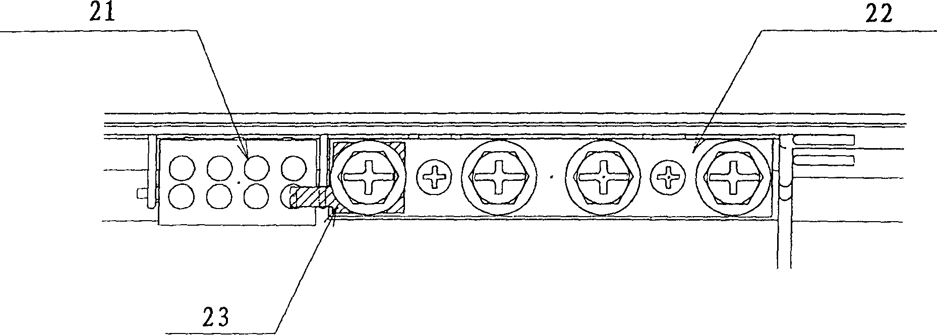
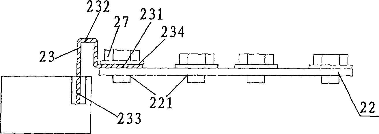
[0015] like Figure 2A , Figure 2B As shown, the insertion terminal portion 21 of the switchboard is constituted by a plurality of holes, and a plurality of through holes 221 are drilled in the copper rod portion 22 of the switchboard. In addition, the conductor 23 for electrically connecting the insertion terminal portion 21 and the copper rod portion 22 is formed by bending, and when viewed from the cross-section thereof, it is formed substantially " ” shape. In addition, a through hole 234 is drilled in the long horizontal plate 231 of the conductor 23, in the state where the through hole 221 and the through hole 234 are aligned, the screw 27 is inserted from the upper direction, the screw 27 is tightened, and the connection with the copper rod is completed. 22. In addition, when the long vertical plate 233 of the conductor 23 is inserted into the insertion termi...


PUM


Abstract

This invention provides a connection structure of plug-in terminal and copper rod earth terminal of a distributor, in which the connection of the plug-in terminal and the copper rod terminal is not by wire but as the conductors of other components, so it's easier for the connection of the plug-in terminal and copper rod pare reducing connecting space of wire. It's easier to remove the plug-in terminal.

Description

technical field [0001] The invention relates to a connection structure between an insertion terminal part of a switchboard and a ground terminal part of a copper rod. Background technique [0002] like figure 1 As shown, the insertion terminal portion 11 and the copper rod portion 12 of a general switchboard are electrically connected by wires 13 . However, this method of connecting with the wires 13 has the following disadvantages. [0003] 1. The wire 13 needs to be connected to both the insertion terminal portion 11 and the copper rod portion 12, which is very troublesome. [0004] 2. The wiring space 14 of the wires 13 is required, and the wiring space in the panel becomes smaller. [0005] 3. When the insertion terminal portion 11 is removed from the switchboard and used, the movable range of the insertion terminal portion 11 is limited to the length of the electric wire 13 connected to the copper rod portion 12 . SUMMARY OF THE INVENTION [0006] In view of the p...

Claims


Application Information

Patent Timeline
IPC IPC(8): H02B1/00H02B1/16H02B1/015
Inventor 寺本健一郎
Owner KAWAMURA ELECTRIC INC
Why Eureka
Try Eureka