


Quick Research
Generate reliable direction feasibility study reports for your R&D in just a few steps.

Technical Q&A
Discover and master advanced knowledge NOW. Basics, ideas, possibilities, all at once.

Find Solutions
As an expert in R&D theories, this can generate solutions to your technical problems instantly.

Evaluate Feasibility
Analyze your overall solution with one click, know your potential R&D risks in advance.

Monitor Landscape
Get weekly tech updates, stay abreast of the latest tech innovations and key insights.
Light tube module for concrete
A technology of pipe assembly and corrugated pipe assembly, which is applied in the field of lightweight pipe assembly for concrete, and can solve the problems of affecting the construction progress, relative fixing and positioning troubles, etc.
- Summary
- Abstract
- Description
- Claims
- Application Information
AI Technical Summary
Problems solved by technology
Method used
Image

Examples
Embodiment Construction
[0050] The present invention will be further described below in conjunction with drawings and embodiments.
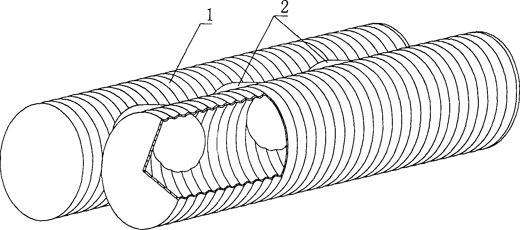
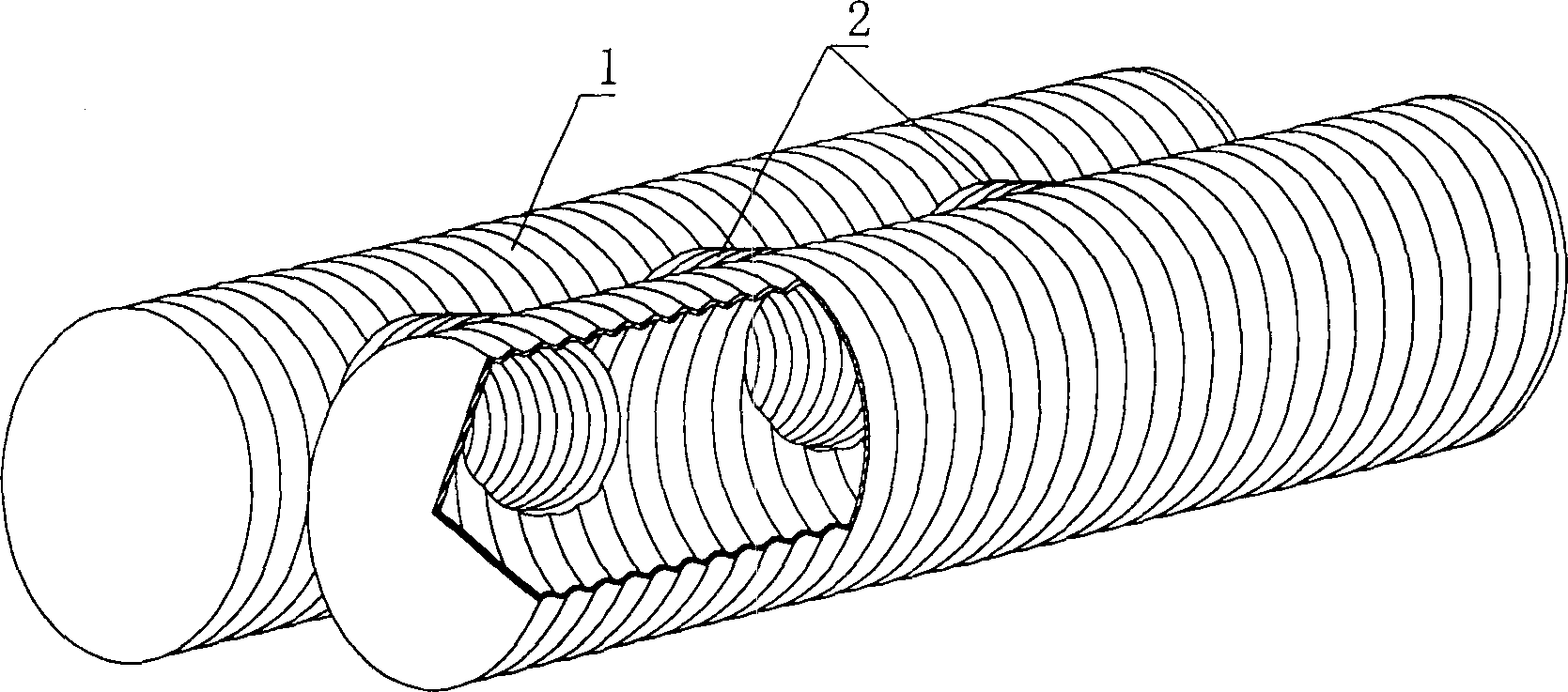
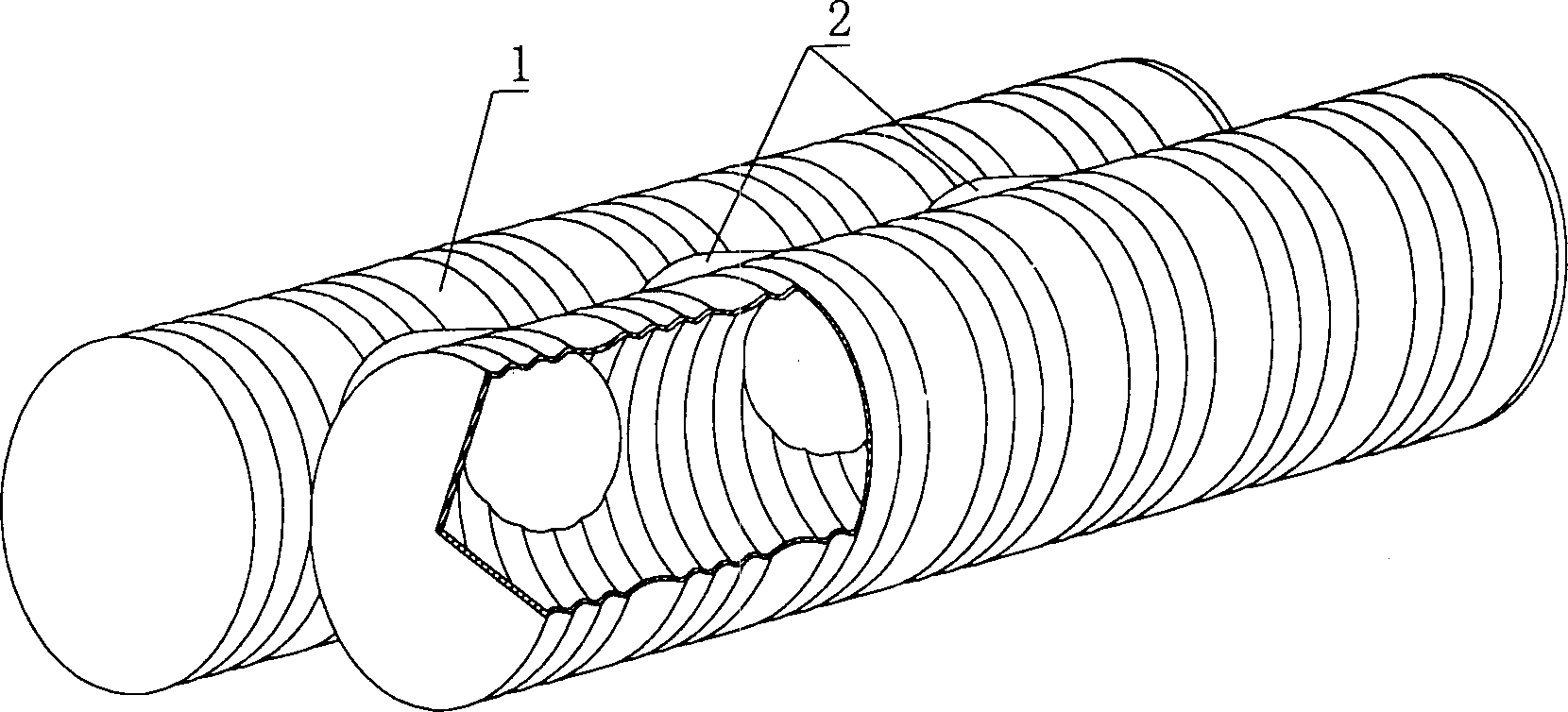
[0051] As shown in the drawings, the present invention includes a lightweight pipe 1, which is a corrugated pipe, and is characterized in that the lightweight pipe assembly is composed of at least two or more than two lightweight corrugated pipes 1, the adjacent There is a connecting pipe 2 between the pipes to horizontally connect the adjacent lightweight corrugated pipes 1 to form a lightweight corrugated pipe assembly, and the connecting pipe 2 and the lightweight corrugated pipe 1 are transversely connected by two pipes intersecting. figure 1 It is a structural schematic diagram of Embodiment 1 of the present invention. figure 1 Among them, 1 is a lightweight corrugated pipe, and 2 is a connecting pipe. In the drawings, those with the same number have the same description. Such as figure 1 As shown, the lightweight pipe assembly consists of two lightweight corruga...
PUM
 Abstract
Description
Claims
Application Information
 - R&D Engineer
- R&D Manager
- IP Professional
- Industry Leading Data Capabilities
- Powerful AI technology
- Patent DNA Extraction
Browse by: Latest US Patents, China's latest patents, Technical Efficacy Thesaurus, Application Domain, Technology Topic, Popular Technical Reports.
© 2024 PatSnap. All rights reserved.Legal|Privacy policy|Modern Slavery Act Transparency Statement|Sitemap|About US| Contact US: help@patsnap.com