Process for preparing hydrogen by catalytic partial oxidation of liquid hydrocarbon
A hydrocarbon catalytic part, liquid hydrocarbon technology, applied in chemical instruments and methods, hydrogen, inorganic chemistry, etc., can solve the problems of low yield of target product hydrogen, high operating temperature, high catalyst cost, etc., and achieve high activity of reaction catalysts , high hydrogen yield and low catalyst cost
- Summary
- Abstract
- Description
- Claims
- Application Information
AI Technical Summary
Problems solved by technology
Method used
Image
Examples
Embodiment 1
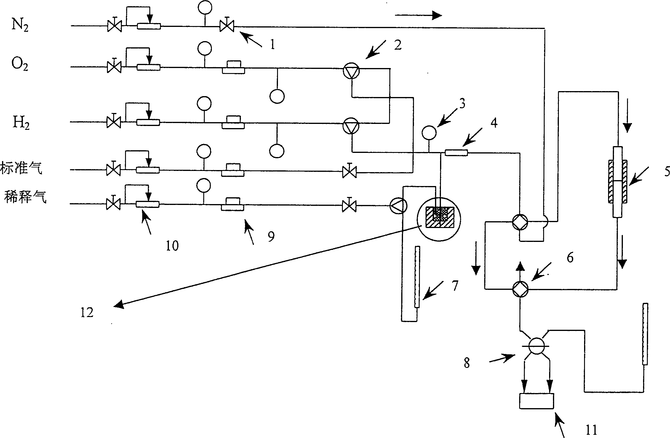
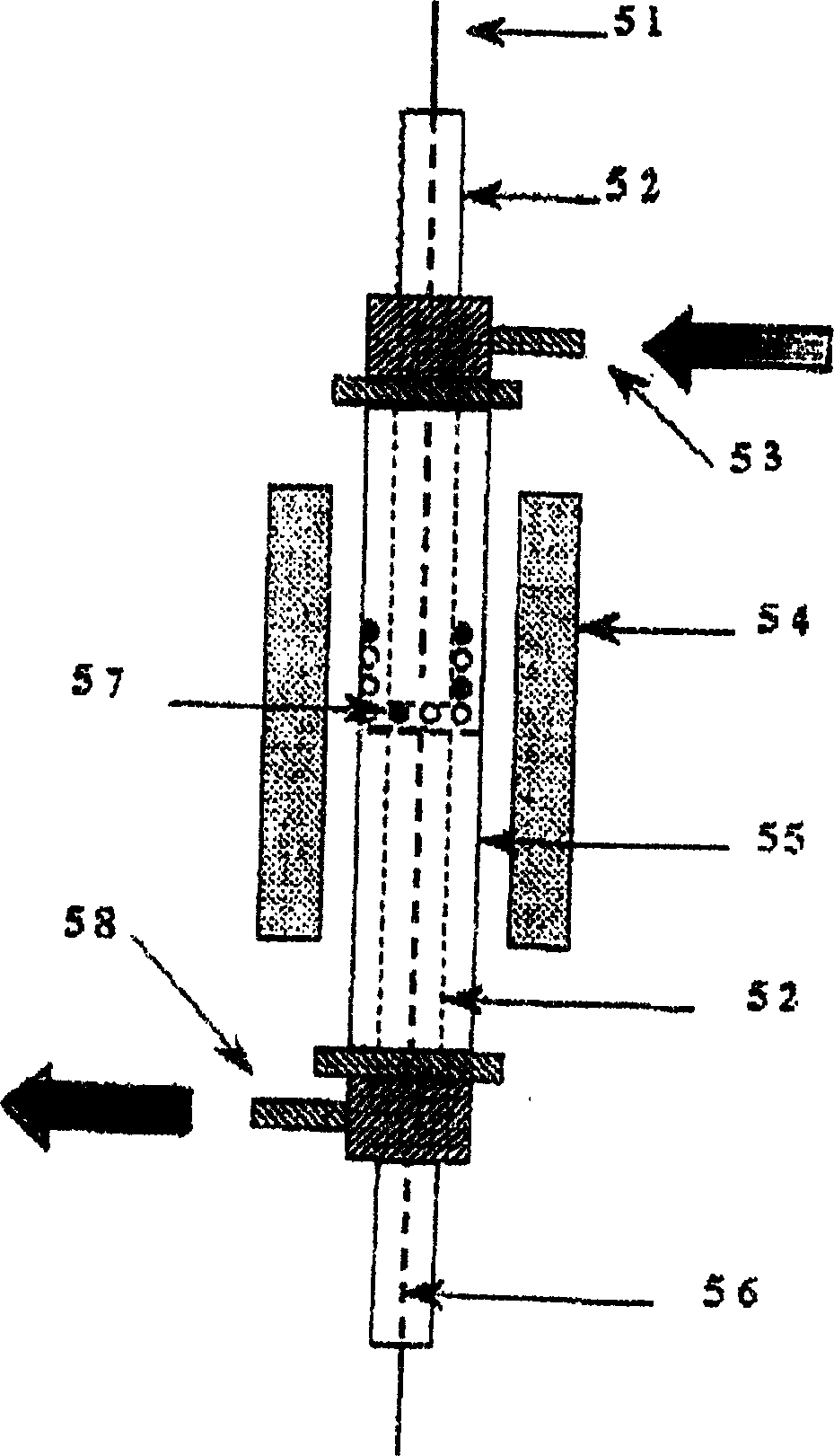
[0028] The reaction main device process structure that the present embodiment adopts is as follows figure 1 As shown, it is mainly composed of flow control equipment, mixer 4, reactor 5, chromatograph 11 as detection equipment and liquid hydrocarbon raw material feeding device 12. The reaction pipeline is a stainless steel pipe, and the liquid hydrocarbon and mixer 4 and reactor 5 The stainless steel pipeline between them is wound with a heating tape, which is heated during the reaction to prevent the condensation of liquid hydrocarbons in the pipeline. Wherein: the flow control equipment includes a stop valve 1, a three-way valve 2, a precision pressure gauge 3, a four-way valve 6, a flow meter 7, a six-way valve 8, a mass flow meter 9, and a steady flow valve 10.
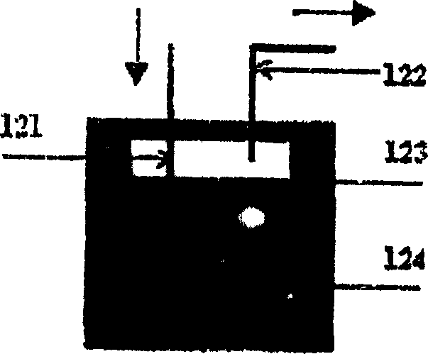
[0029] diagram 2-1 It is a schematic diagram of the structure of the feeding device for liquid hydrocarbons. The liquid hydrocarbon feedstock is placed in an airtight glass container 124, and then placed in a co...
Embodiment 2
[0037] The difference from Example 1 is:
[0038] Adopt the Ni / Al prepared by embodiment 1 2 o 3 As a reaction catalyst, the partial oxidation reaction was carried out under the conditions of O / C of 1.03, 1.1, 1.3, 1.5, and 1.7, respectively. The hydrogen selectivity in the reaction varies with temperature as Figure 4 shown. When O / C=1.7, the hydrogen production rate is 68%, and when O / C=1.03, the hydrogen production rate can reach 95%.
Embodiment 3
[0040] 1) Preparation of Ni / Al with a loading of 5-10wt% 2 o 3 catalyst.
[0041] 10g Al 2 o 3 0.4M Ni(NO 3 ) 2 20 ml of the solution was dried at 100° C. and calcined at 850° C. for 4 hours to obtain the desired catalyst. The Ni loading of the active component was about 5 wt%.
[0042] 10g Al 2 o 3 0.5M Ni(NO 3 ) 2 20 ml of the solution was dried at 100° C. and calcined at 850° C. for 4 hours to obtain the desired catalyst. The Ni loading of the active component was about 7 wt%.
[0043] 10g Al 2 o 3 0.8M Ni(NO 3 ) 2 20 ml of the solution was dried at 100° C. and calcined at 850° C. for 4 hours to obtain the desired catalyst. The Ni loading of the active component was about 10 wt%.
[0044] 2) Partial oxidation hydrogen production reaction
[0045] The loadings prepared in this example are 5wt%, 7wt%, 10wt% Ni / Al 2 o 3 catalyst, at a space velocity of 1.0 x 10 4 l / kg / h, 1.8×10 4 l / kg / h, 2.8×10 4 l / kg / h, 850°C, O / C=1.08, He / C 7 h 16 Under the condition of...
PUM
| Property | Measurement | Unit |
|---|---|---|
| specific surface area | aaaaa | aaaaa |
Abstract
Description
Claims
Application Information
 - R&D Engineer
- R&D Manager
- IP Professional
- Industry Leading Data Capabilities
- Powerful AI technology
- Patent DNA Extraction
Browse by: Latest US Patents, China's latest patents, Technical Efficacy Thesaurus, Application Domain, Technology Topic, Popular Technical Reports.
© 2024 PatSnap. All rights reserved.Legal|Privacy policy|Modern Slavery Act Transparency Statement|Sitemap|About US| Contact US: help@patsnap.com


