Optical transmission apparatus

A technology of optical transmission and equipment, applied in transmission systems, electromagnetic wave transmission systems, electrical components, etc., can solve the problems of waste of cross-connection capabilities and high costs of business cross-connect boards

Inactive Publication Date: 2005-12-28
UTSTARCOM TELECOM CO LTD
View PDF0 Cites 0 Cited by
  • Summary
  • Abstract
  • Description
  • Claims
  • Application Information

AI Technical Summary

Problems solved by technology

If there are fewer service access boards inserted into the system, the cross-connect capability on the service cross-connect board will obviously be wasted.
Therefore, when the equipment based on the centralized cross-connect system is used in occasions with a small amount of service access, the cost will obviously be high

Method used


Image

  • Optical transmission apparatus
  • Optical transmission apparatus
  • Optical transmission apparatus

Examples


Embodiment Construction

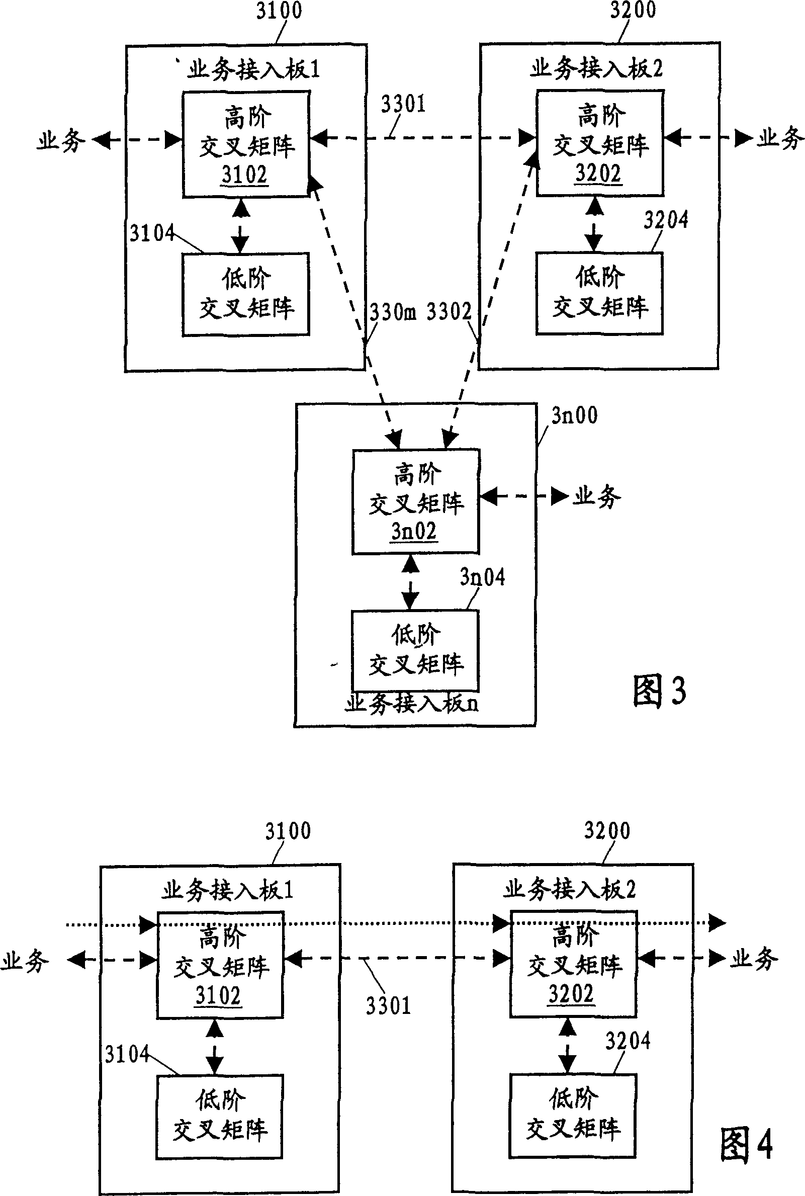
[0026] FIG. 3 is a schematic diagram of an optical transmission device based on a distributed crossover system according to the present invention. Only three service access boards 3100, 3200, and 3n00 are shown in the figure. In fact, there can be any number of service access boards in an optical transmission device. Corresponding board positions of these service access boards are connected in pairs through backplane service buses 3301, 3302...330m. For each service access board, the components of the traditional service access board are omitted in the figure, and only the crossover matrix set in the service access board in the present invention is shown, including high-order crossover matrices 3102, 3202... ..3n02 and low order crossover matrices 3104, 3204...3n04. Correspondingly, in the figure, the arrows indicating service access and sending directly point to the high-order cross-connect matrix 3102, 3202...3n02. In fact, services pass through other components of the ser...


PUM


Abstract

The invented device uses distributed intercross architecture. The architecture discards the service overlapping board in traditional optical transmission device, and cross-interaction matrix is addedto each service access board. The service bus is setup between each position of service access board in designing backboard. The scheduling mode based on centralized intercross service is changed to scheduling mode based on distributed intercross service so as to realize allocation of system intercross capacity based on need. The invention raises performance cost ratio of system, and realizes optical transmission device in small size, large capacity and low cost.

Description

technical field [0001] The present invention relates to optical transmission equipment. Background technique [0002] Optical transmission equipment is used for optical transmission network, and its logical functional components include regenerators, multiplexing equipment (including terminal multiplexing equipment TM and add-drop multiplexing equipment ADM) and cross-connect equipment. Common optical transmission equipment includes SDH (Synchronous Digital Hierarchy) equipment, SONET (Synchronous Optical Network) equipment and MSTP (Multi-Service Transmission Platform) equipment, etc. [0003] In specific optical transmission equipment, the above-mentioned logical functional components and other auxiliary components and circuits are often integrated into various boards according to the modular design, and these boards can be inserted into the slots on the subrack (hereinafter referred to as board positions). The bits are connected to other necessary board bits through the ...

Claims


Application Information

Patent Timeline
Patent Type & Authority Patents(China)
IPC IPC(8): H04B10/27H04Q3/52
Inventor 刘中书
Owner UTSTARCOM TELECOM CO LTD
Why Eureka
Try Eureka