Standpipe inlet for enhancing particulate solids circulation for petrochemical and other processes

A standpipe and particle technology, applied in chemical instruments and methods, petroleum industry, chemical/physical processes, etc., can solve problems such as bubble inhalation and air consumption

Inactive Publication Date: 2005-11-16
SHELL INT RES MAATSCHAPPIJ BV
View PDF1 Cites 0 Cited by
  • Summary
  • Abstract
  • Description
  • Claims
  • Application Information

AI Technical Summary

Problems solved by technology

The main drawback of the prior art is that the standpipe inlet design aims to reduce the amount of gas entrained into the standpipe, in fact, this design instead encourages a large number of air bubbles to be sucked in
First, gas entrainment from the stripper into the regenerator represents a loss of hydrocarbon product, which may have been reduced to product
Second, the entrained hydrocarbons have been burned in the regenerator, and this combustion consumes the limited air in the regenerator and generates excess heat that must be removed

Method used


Image

  • Standpipe inlet for enhancing particulate solids circulation for petrochemical and other processes
  • Standpipe inlet for enhancing particulate solids circulation for petrochemical and other processes
  • Standpipe inlet for enhancing particulate solids circulation for petrochemical and other processes

Examples


Embodiment Construction

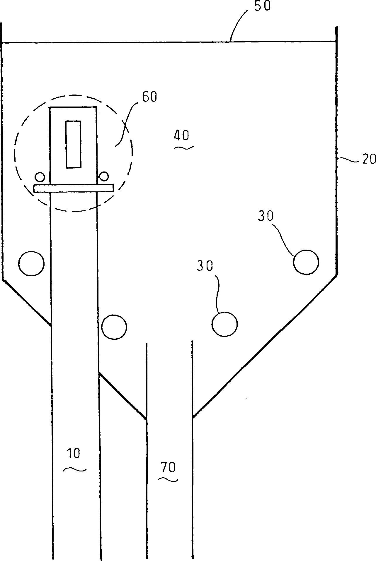
[0019] refer to figure 1 , figure 1 A cross-sectional view of the lower portion of a conventional regenerator vessel 20 of an FCC unit provided with a regenerator standpipe 10 including an inlet portion 60 for intake of regenerated catalyst according to the present invention. Spent catalyst is transported from the stripper (not shown) through a conventional residual catalyst transfer line 70 and into regenerator 20 where coke deposited on the catalyst is fed by the primary air grid. The air burns off. Air from the grid 30 and the resulting combustion gases rise through the regenerator to fluidize the catalyst within the fluidized bed 40 . Combustion gases and entrained regenerated catalyst are separated in the upper part of the regenerator by a cyclone (not shown). Combustion gases are exhausted from the upper part of the regenerator, and regenerated catalyst separated by a cyclone (not shown) is returned to the fluidized bed 40 . The typical density of the fluidized bed 4...


PUM


Abstract

Apparatus comprising means for keeping a bed of particulate solids in a fluidized bed mode in a vessel, a conduit for transferring said particulate solids into the resulting fluidized bed and a standpipe, protruding into said fluidized bed, for transferring particulate solids out of the fluidized bed, wherein a disk surrounding the standpipe is present below the upper part of the standpipe, which upper part the standpipe comprises an inlet for receiving solids from the fluidized bed.

Description

technical field [0001] The present invention relates to a standpipe inlet configuration for enhanced particulate circulation and reduced gas transport suitable for use in fluid catalytic cracking (FCC) units and other reactions such as sulfur cokers, flexicokers and In a fluidized bed coal burner, a large amount of particulate solids circulates between different vessels connecting the standpipe and riser. Background technique [0002] A regenerator, a riser reactor and a stripper (stripper) are usually included in a conventional fluidized catalytic cracking (FCC) reaction, as shown in US Patent 5562 818 to Hedrick, subdivided regeneration The catalyst remains in the regenerator and contacts the hydrocarbon feedstock in the lower portion of the reactor riser. Hydrocarbon feedstock and steam enter the riser through feed nozzles. A mixture of feed, steam, and regenerated catalyst at a temperature of about 200°C to about 700°C flows upward through the riser reactor and convert...

Claims


Application Information

Patent Timeline
Patent Type & Authority Patents(China)
IPC IPC(8): B01J8/00B01J8/24B01J8/28C10G11/18F23C10/24
CPCB01J8/28C10G11/18F23C10/24C10G11/182B01J8/0015B01J8/003B01J2208/00761B01J8/1872B01J2208/00769
Inventor 戴维·J·布罗斯腾陈岳孟
Owner SHELL INT RES MAATSCHAPPIJ BV
Why Eureka
Try Eureka