Transport devices and methods for film bags

A transfer device, film bag technology, applied in the direction of transmission, transportation and packaging, packaging, etc., can solve problems such as discontinuity

Inactive Publication Date: 2005-10-19
INDAG GES FUER INDBEDARF & BETRIEBS
View PDF0 Cites 0 Cited by
  • Summary
  • Abstract
  • Description
  • Claims
  • Application Information

AI Technical Summary

Problems solved by technology

This results in a discontinuous operation, since the supplied quantities corresponding to the number of rows for parallel supply must always be conveyed simultaneously while the conveying device is a...

Method used


Image

  • Transport devices and methods for film bags
  • Transport devices and methods for film bags
  • Transport devices and methods for film bags

Examples


Embodiment Construction

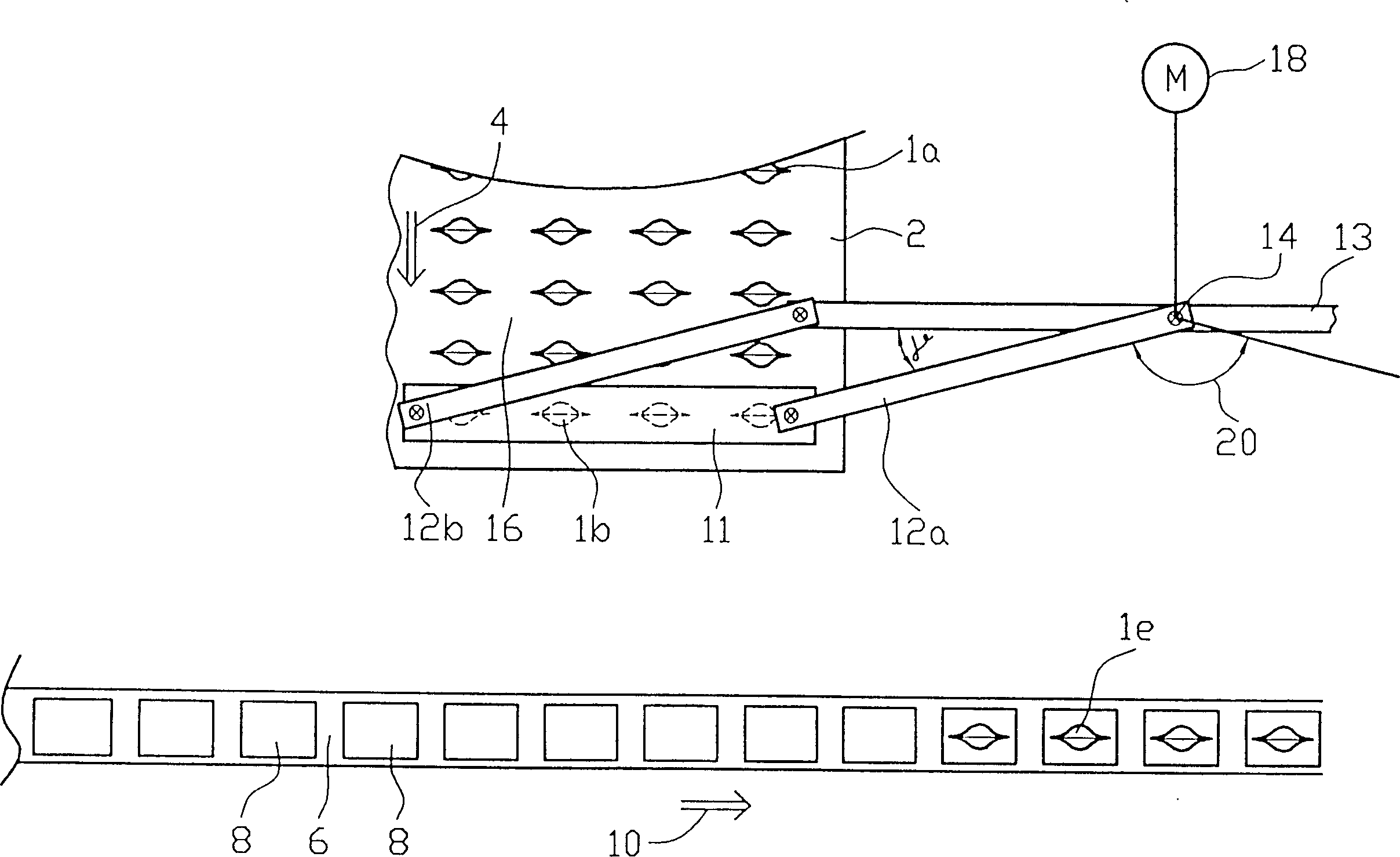
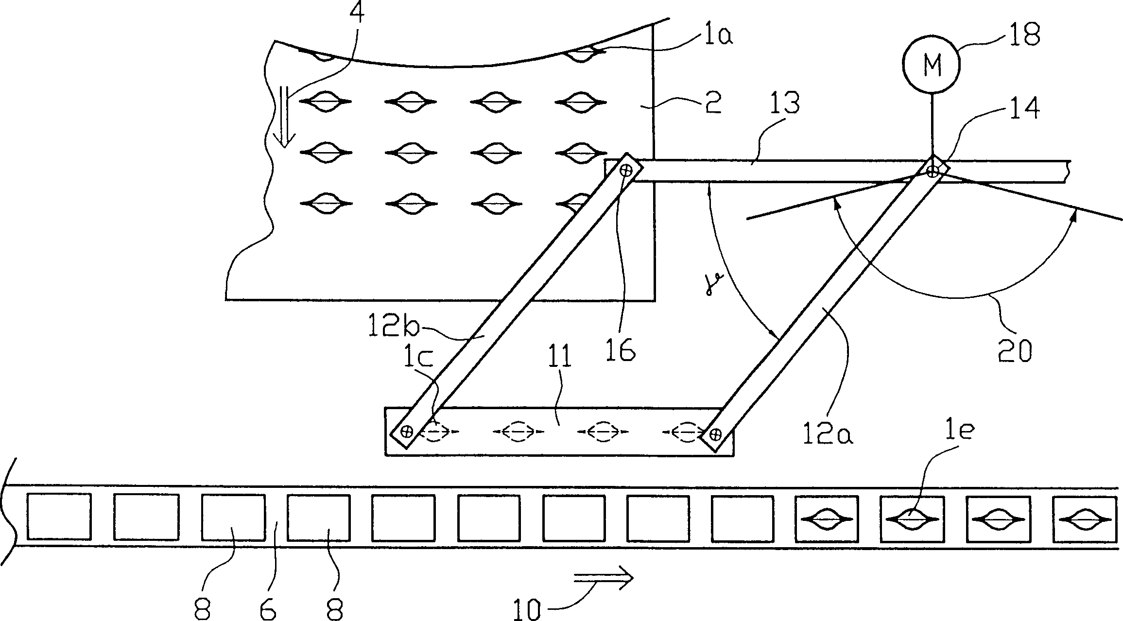
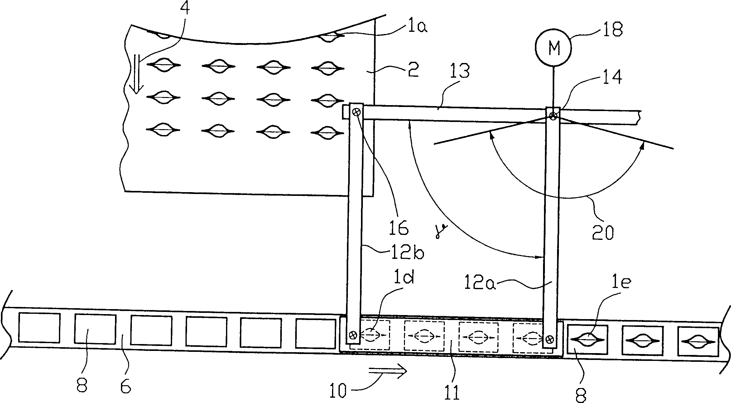
[0028] Figure 1a to Figure 1c The translocation region is shown. Such a transfer area can be found, for example, in a beverage filling system. The filled and closed beverage film bag 1a is transported by the transfer device to a conveying device which, for example, transports the beverage film bag to a beverage tube installation station.

[0029] The filled and closed beverage film pouches 1 a are supplied by a supply device 2 in a supply direction 4 .

[0030] 13 denotes a conveyor having pivotable lever arms 12a, 12b hinged thereto at pivot points 14 and 16. An electric motor 18 is provided for providing pivotal movement in the direction of arrow 20 . 11 denotes a transverse bar, which has a bottom with clamping means, which are not expressly shown in Figures 1a to 1c . In Fig. 1, the film bag 1b transferred by the transverse bar 11 is indicated by dashed lines. The transverse bar 11, the two lever arms 12a, 12b and the conveyor 13 form a parallelogram with a variabl...


PUM


Abstract

The invention relates to a method and to a device for transferring film bags that are advanced to a transfer station in a plurality of parallel rows, to a transport device that transports the film bags in a continuous row in an essentially transverse relation to the feed direction. The film bags to be transferred are preaccelerated in the direction of movement of the transport device.

Description

technical field [0001] The invention relates to a method for the transfer of film bags, which are supplied by a supply device in parallel rows, transferred to a conveying device, which in turn transports the film bags in a continuous row; Apparatus for implementing the above method. Background technique [0002] Today, film bags used as packaging are usually handled automatically, eg filled, closed and further processed. Such a film bag is composed of two side films, the three sides of the two films are sealed to each other, and a bottom film is sealed between the fourth side of the two films, because when the bottom film is unfolded, the film bag A space is formed in which to fill the product. [0003] On such automatic process lines, often several film bags are processed simultaneously side by side. For example, a plurality of film bags are simultaneously opened on a filling device, conveyed by a conveying device while being filled, and then conveyed and simultaneously ...

Claims


Application Information

Patent Timeline
IPC IPC(8): B65B35/36B65B43/36B65G47/90F16H21/44
CPCB65G47/904B65G47/907
Inventor 汉斯-彼得·维尔德埃伯哈德·克拉夫特
Owner INDAG GES FUER INDBEDARF & BETRIEBS
Why Eureka
Try Eureka