
Position detecting device

A detection device and light detection technology, which is applied in the field of optical position detection devices, can solve the problems of inability to judge the light irradiation area, high technical level, troubles in use, etc.

Inactive Publication Date: 2005-10-05
OPTO TECH
View PDF1 Cites 0 Cited by
  • Summary
  • Abstract
  • Description
  • Claims
  • Application Information

AI Technical Summary

Problems solved by technology

[0009] Although the detection of the moving position is a series of judgment combinations, it can also be found that due to the existence of the space 288, the light irradiation area may not be able to judge during its movement within its range, so as to reduce its sensitivity or cannot The situation of reaction occurs, which will cause some troubles in use for some occasions that require high accuracy and sensitivity.
[0010] Of course, in order to avoid the above-mentioned regret, the width of the gate hole 14 can also be narrowed to a size that cannot accommodate two photodetection elements 281, 282 in one light irradiation area 182, but this needs to be done in a very small shield. Each grid hole 14 is precisely chiseled on the cover 12, which not only has a high technical level, but also greatly increases the production cost.
[0011] Therefore, how to design a novel position detection device, which can effectively reduce the result of its sensitivity reduction due to the existence of space, is the key point of the present invention.

Method used


Image

  • Position detecting device
  • Position detecting device
  • Position detecting device

Examples


Embodiment Construction

[0058] In order to have a further understanding and recognition of the structural features and the achieved effects of the present invention, a detailed description will be made with a preferred embodiment in conjunction with the accompanying drawings, as follows:

[0059] First, see Figure 4 , is a schematic diagram of the light detection action of a preferred embodiment of the position light detection device of the present invention; The detection elements 481-484, such as the parallelogram light detection elements shown in this embodiment, each of the parallelogram light detection elements 481-484 are arranged in a mutual flat manner, although two parallelograms There is still a space 488 between the light detection elements 481-484, but there is a part of the active area of ​​the light detection element at the vertical extension position (the direction of the dashed arrow A) of each space 488, as shown in the figure for example The right side of the light detecting eleme...


PUM


Abstract

An optical position detecter unit is composed of a light source, a mask with multiple orifices for passing the light beam from light source through them, and an optical detector with multiple rectangular optical detecting elements for absorbing said light beam passing through said orifices. It features that an acting area for an optical detecting element naturally exists at the vertically extended position of a gap space between two optical detecting elements for higher correctness and sensitivity.

Description

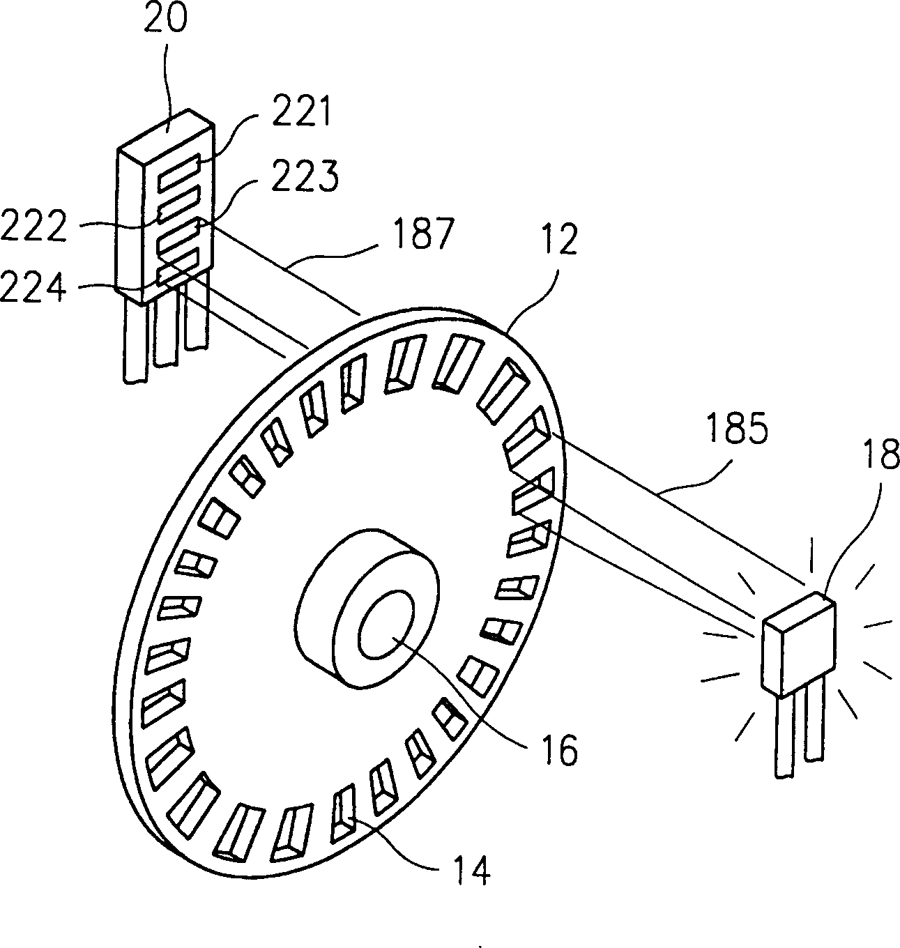
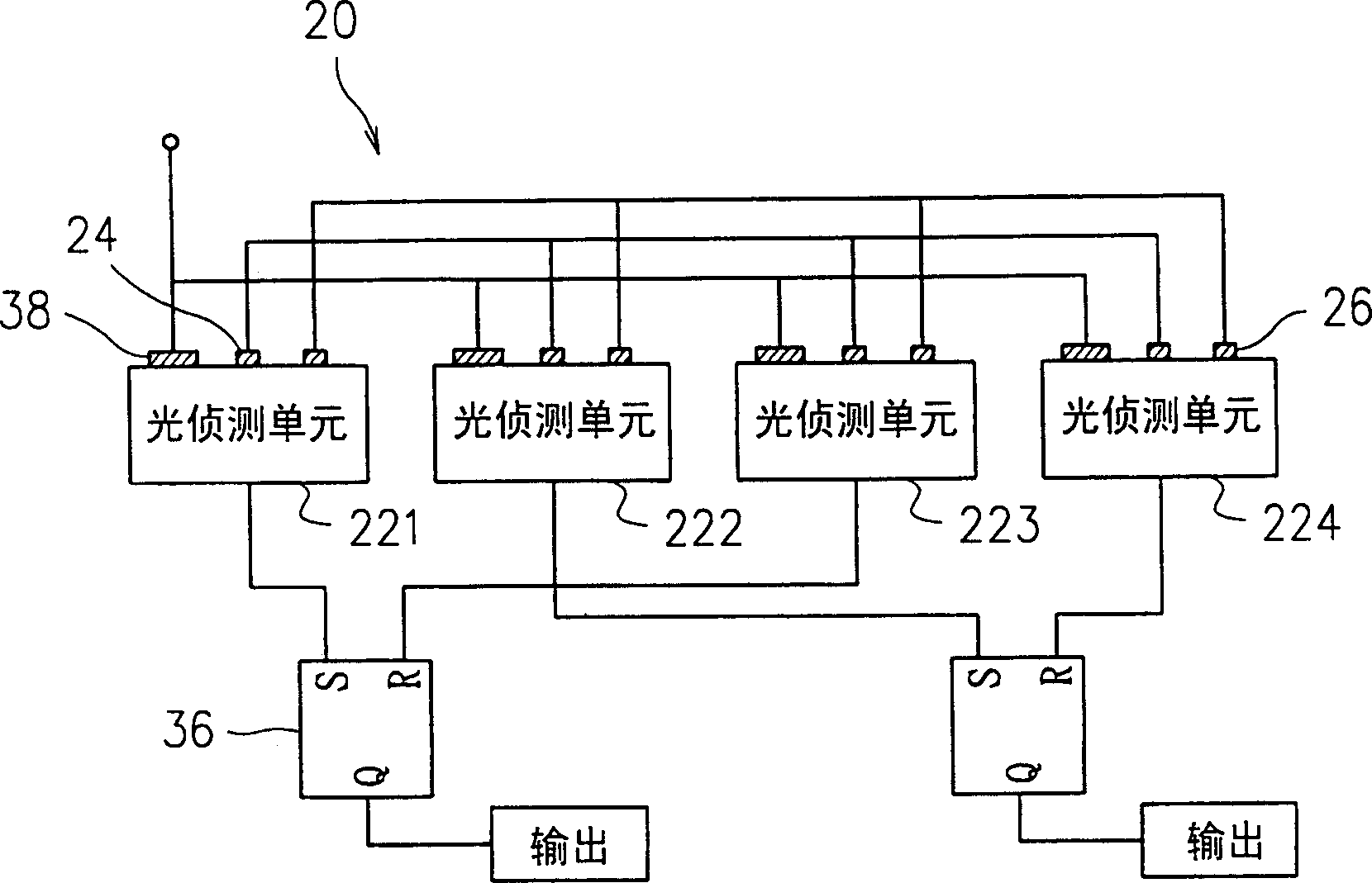
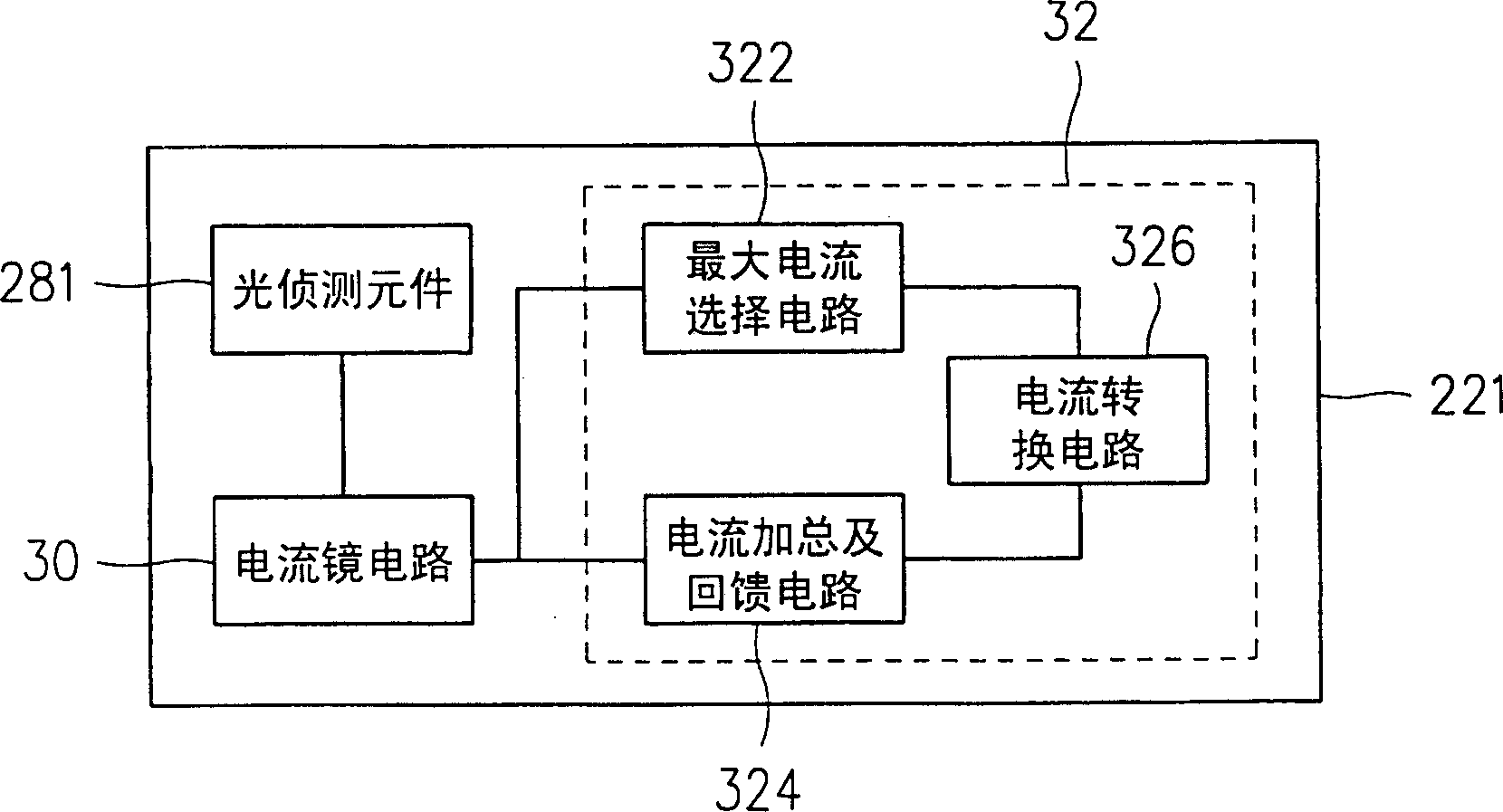
technical field [0001] The invention relates to a position detection device, especially an optical position detection device, which can be used to reduce the defects of misjudgment or low sensitivity of the light detection device due to the existence of a space. Background technique [0002] Press, the optical position detection device has the advantages of high sensitivity, high resolution, easy signal identification and noise reduction, so it is widely used in general computer mice, cursor indicators, knobs or consumer electronics products middle. [0003] However, the industry has also developed various position detection devices in response to the characteristics and product requirements of position detection devices, such as the Taiwan Patent Publication No. 523082 "Detection Device for Detecting Position and Angle Changes" approved by the applicant of the present invention ". [0004] see figure 1 , Figure 2A and Figure 2B , are respectively the three-dimensiona...

Claims


Application Information

Patent Timeline
Patent Type & Authority Patents(China)
IPC IPC(8): G01B11/02
Inventor 萧淳方林信翔沈志雄林三宝
Owner OPTO TECH
Learn More