Fluid compression apparatus

A technology for compressing equipment and fluids, applied in mechanical equipment, components of pumping devices for elastic fluids, liquid fuel engines, etc., can solve problems such as lack of good manufacturing methods, increased manufacturing costs, and reduced fluid volume.

Inactive Publication Date: 2005-08-24
SAMSUNG GWANGJU ELECTRONICS CO LTD
View PDF0 Cites 0 Cited by
  • Summary
  • Abstract
  • Description
  • Claims
  • Application Information

AI Technical Summary

Problems solved by technology

Therefore, in the conventional fluid compressing device, since the high-pressure fluid remaining in the fluid discharge port 32 generates the clearance volume of the cylinder bore 11 in each stroke cycle, the amount of fluid sucked into the cylinder bore 11 is reduced, and lead to inefficiency
[0012] Moreover, since the conventional fluid compressing equipment must use the suction valve 33 and the discharge valve 34 having complicated structures to open the fluid suction port 31 and the fluid discharge port 32, it is complicated to assemble the compressor device
Also, there is no good manufacturing method for this, and the structure leads to increased manufacturing costs

Method used


Image

  • Fluid compression apparatus
  • Fluid compression apparatus
  • Fluid compression apparatus

Examples


Embodiment Construction

[0030] Preferred embodiments of the present invention will be described in detail below with reference to the accompanying drawings.

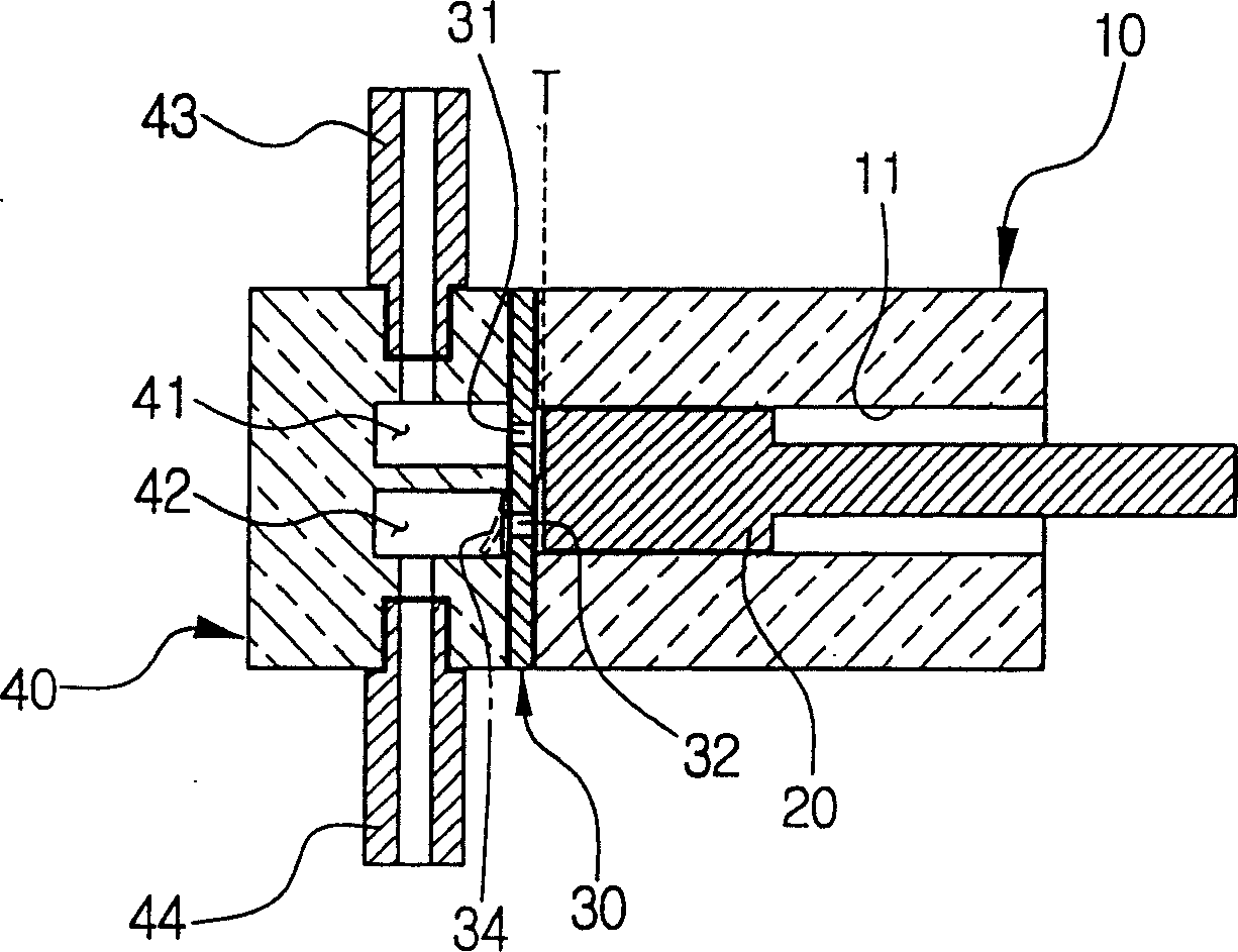
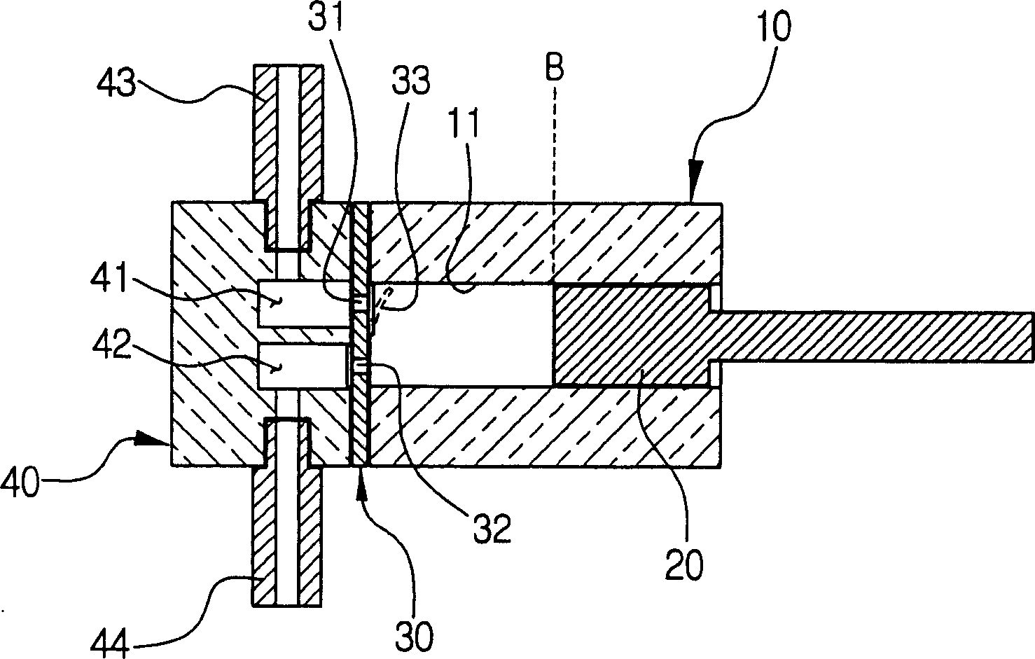
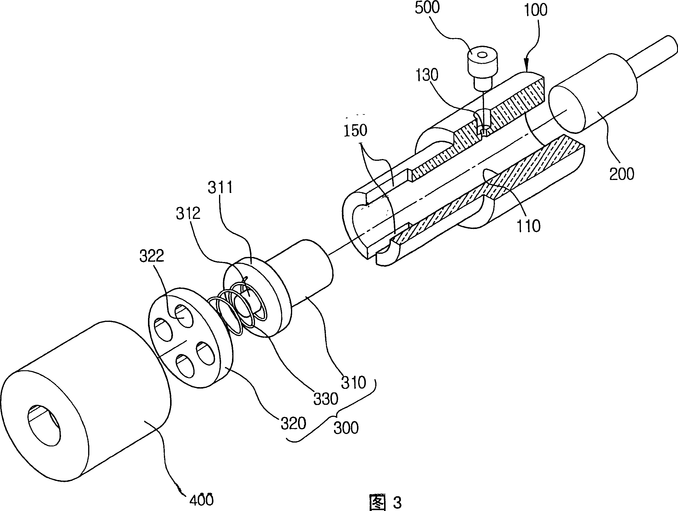
[0031] Fig. 3 is a cutaway exploded perspective view showing a fluid compressing device according to a first preferred embodiment of the present invention. Figure 4 to Figure 6 is a sectional view illustrating the result and operation of the fluid compressing apparatus according to the first preferred embodiment of the present invention shown in FIG.

[0032] Figure 3 to Figure 6 As shown, the fluid compression device according to the present invention includes a cylinder 100 , a piston 200 , a discharge valve assembly 300 and a cylinder head 400 .

[0033]The cylinder block 100 includes a cylinder bore 110 having a predetermined diameter and passing through the cylinder block 100 longitudinally, at least one fluid suction port 130 passing through the cylinder bore 110 at a right angle with respect to the cylinder bore 110, at least a pair o...


PUM


Abstract

An apparatus for compressing fluid comprises a cylinder bore longitudinally penetrating a cylinder block a suction port penetrating to the cylinder bore, and a pair of slot-shaped fluid discharge having one opening at an end portion of the cylinder bore; a piston; a discharge valve assembly movably disposed at the cylinder bore to selectively open and close the fluid discharge ports of the cylinder block, the discharge valve assembly including a valve piston having a flange for limiting movement of the discharge valve assembly; a cylinder head defining a discharge chamber communicating with the fluid discharge ports, the cylinder head having a fluid discharge passage from the discharge chamber. The fluid suction port is selectively opened by the piston reciprocally moving in the cylinder bore to draw in fluid, which is discharged through the fluid discharge ports opened by the movement of the valve piston as the pressure of the fluid in the cylinder bore increases beyond a predetermined threshold. The compressed fluid is fully discharged, and clearance volume can be eliminated or minimized.

Description

technical field [0001] The present invention relates generally to a compression device, and more particularly to a device for compressing, pumping and discharging fluid using reciprocating linear motion of a piston. Background technique [0002] A typical example of a conventional device for fluid compression is shown in figure 1 and figure 2 middle. [0003] figure 1 and figure 2 is a schematic cross-sectional view showing the structure and operation of conventional equipment for fluid compression. Number 10 represents a cylinder block among the figure, 20 represents a piston, 30 represents a valve plate, and 40 represents a cylinder head. [0004] Such as figure 1 and figure 2 As shown, the cylinder block 10 has a cylinder bore 11 having a predetermined diameter and extending longitudinally through the block. The piston 20 is installed in the cylinder bore 11 of the cylinder 10 and can reciprocate therein. [0005] The valve plate 30 is installed close to the c...

Claims


Application Information

Patent Timeline
Patent Type & Authority Patents(China)
IPC IPC(8): F04B7/04F04B37/00F04B39/10F04B53/10
CPCF04B39/102F04B7/04
Inventor 金贵权李成泰张京台
Owner SAMSUNG GWANGJU ELECTRONICS CO LTD
Why Eureka
Try Eureka