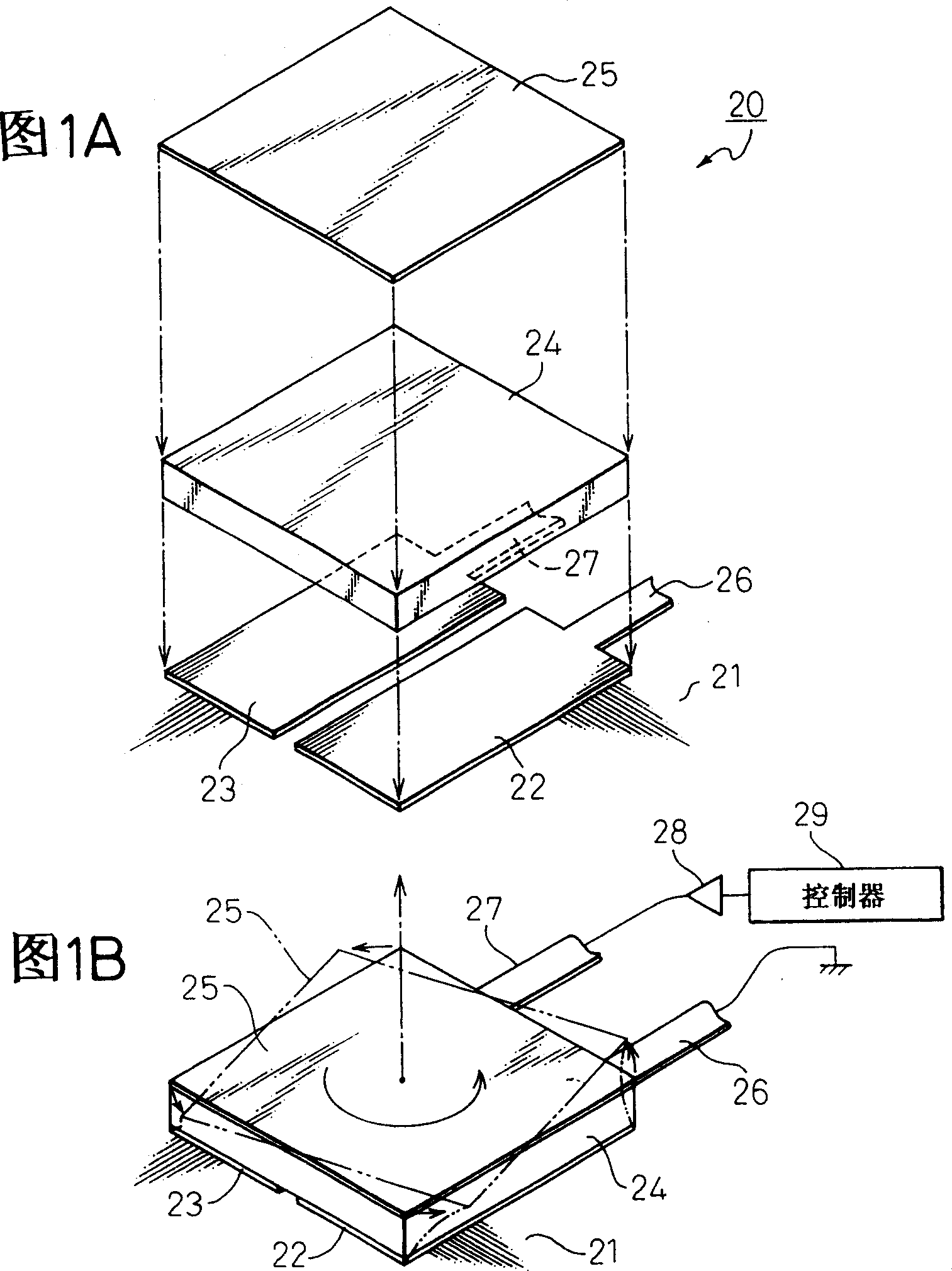
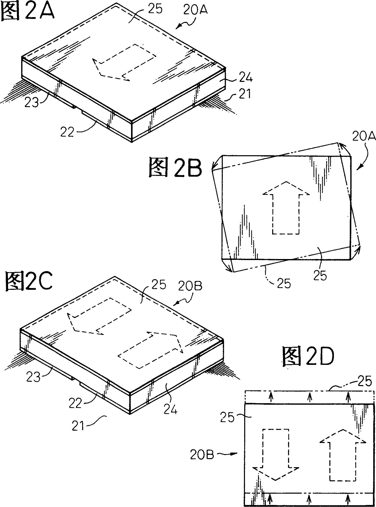
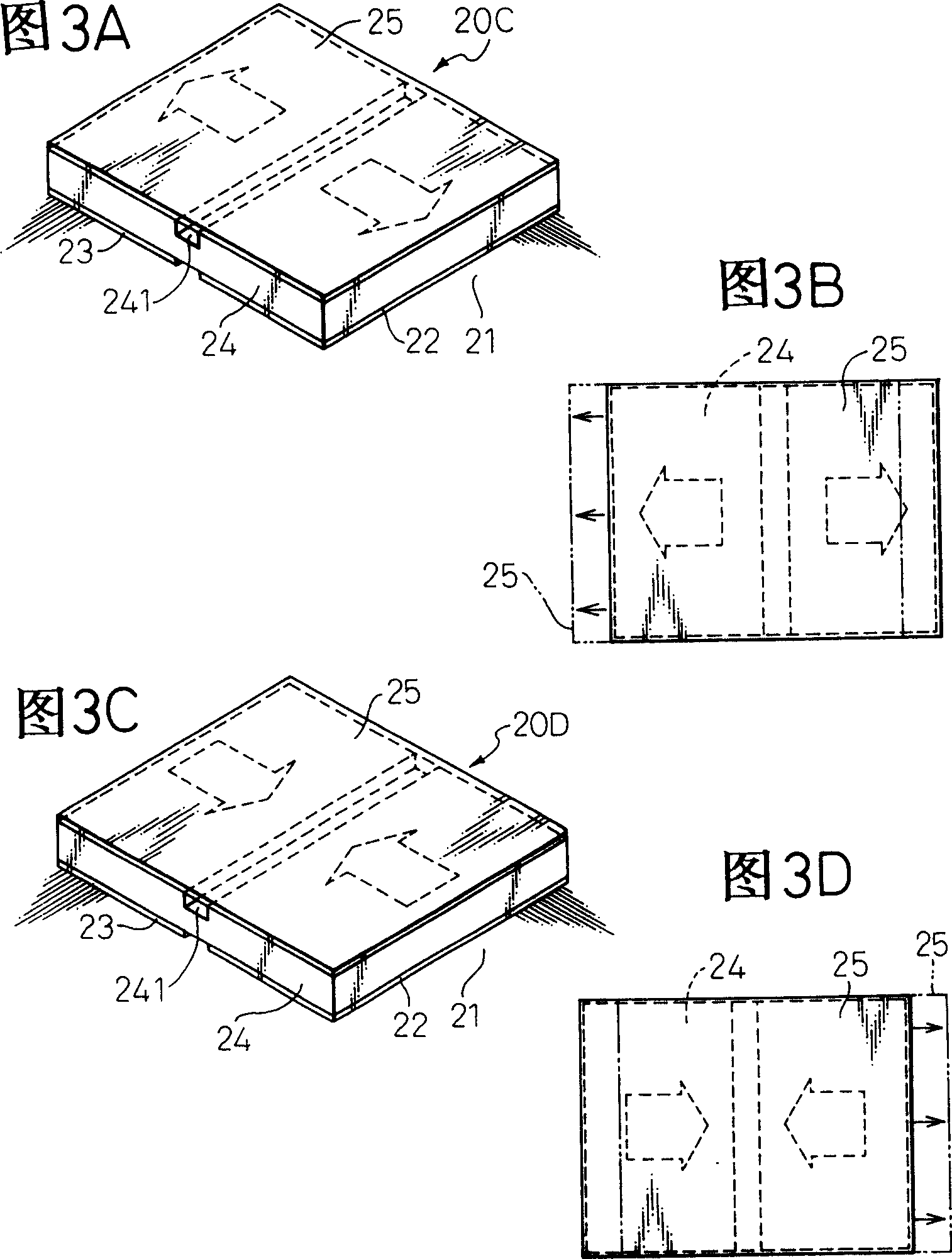
Actuator using piezoelectric element and magnetic head positioning mechanism using said actuator

A piezoelectric element and positioning mechanism technology, applied in piezoelectric effect/electrostrictive or magnetostrictive motors, electrical components, generators/motors, etc., and can solve problems such as high dimensional accuracy

Inactive Publication Date: 2005-05-25
TOSHIBA STORAGE DEVICE CORP
View PDF2 Cites 0 Cited by
  • Summary
  • Abstract
  • Description
  • Claims
  • Application Information

AI Technical Summary

Problems solved by technology

In addition, the machining of the arm also requires high dimensional accuracy and also requires a coupling plate with considerable stiffness in expansion and contraction
The problem that arises is that in order to obtain the predetermined stroke in the head positioning mechanism, considerable force is required

Method used


Image

  • Actuator using piezoelectric element and magnetic head positioning mechanism using said actuator
  • Actuator using piezoelectric element and magnetic head positioning mechanism using said actuator
  • Actuator using piezoelectric element and magnetic head positioning mechanism using said actuator

Examples


Embodiment Construction

[0161] Before describing the preferred embodiment, a description with Figures 24 to 29 A common head actuator for the head positioning mechanism shown.

[0162] It has been proposed that in conventional disk drives, a second actuator which follows the magnetic track is mounted on the front end of the head actuator arm. This second actuator is capable of finely moving the magnetic head at the front end of the arm independently of the movement of the magnetic head actuator.

[0163] Figure 24 A head actuator disclosed in JP-A-3-69072 is shown, in which, in addition to the main actuator 110 of the magnetic disk drive 100, there is a sub-actuator 120 mounted on the front end of an arm 111. The sub-actuator 120 is adapted to slowly move the magnetic head 114 using two multilayer piezoelectric elements 123 . The sub-actuator 120 includes two multi-layer piezoelectric elements, and each piezoelectric element 123 is composed of a plurality of piezoelectric elements adapted to mov...


PUM


Abstract

An actuator includes a shear-type piezoelectric element of predetermined thickness and a counter electrode formed on two spaced electrodes on a base member. When a voltage is applied between these two electrodes, the counter electrode is moved according to the polarization direction of the shear type piezoelectric element. The counter electrode thus constitutes the operative part of the actuator.

Description

technical field [0001] The present invention relates to an actuator using a piezoelectric element and a magnetic head positioning mechanism using the actuator. More particularly, the present invention relates to an actuator using a piezoelectric element capable of high-precision positioning and a magnetic head positioning mechanism using the same. Background technique [0002] In recent years, the precision of information equipment has increased, and an actuator capable of operating over a small distance has been required. For example, actuators that correct the focus of an optical system or control the tilt angle of an optical system, or magnetic head actuators of printers and magnetic disk drives are required to be able to control their operations with high precision. [0003] A disk drive is a key device in multimedia equipment, and the market for the disk drive has expanded in recent years. It has been demanded to develop a large-capacity disk drive for use with a mult...

Claims


Application Information

Patent Timeline
Patent Type & Authority Patents(China)
IPC IPC(8): G11B21/02G11B5/55G11B21/10H02N2/02H02N2/04
CPCG11B5/5552G11B21/106H10N30/208G11B5/483G11B5/5521G11B21/16G11B2220/2516
Inventor 小金泽新治公平彻山田朋良植松幸弘野口忠良中野寿阪本竜马井上淳一铃木彻也
Owner TOSHIBA STORAGE DEVICE CORP
Why Eureka
Try Eureka