
Crank axle with oil-filter

A technology for oil filters and crankshafts, which is applied in the installation/connection of crankshafts, lubricant purification devices, lubricating parts, etc. It can solve the problems of increased weight and inability to ensure separation performance, so as to improve strength and prevent foreign matter from passing through the filter , The effect of improving durability

Inactive Publication Date: 2005-05-11
HONDA MOTOR CO LTD
View PDF1 Cites 0 Cited by
  • Summary
  • Abstract
  • Description
  • Claims
  • Application Information

AI Technical Summary

Problems solved by technology

[0006] However, in the lubricating oil passage device described above, the lubricating oil storage chamber with a relatively large volume is provided on the crankpin, and the load transmitted from the piston through the connecting rod acts on the crankpin. Therefore, the strength of the crankpin must be increased, causing the crankshaft to upsizing, weight increase
In addition, although the dust and the like in the lubricating oil supplied to the bearing are separated by centrifugal force, the same level of separation performance as when using a filter cannot be ensured.

Method used


Image

  • Crank axle with oil-filter
  • Crank axle with oil-filter
  • Crank axle with oil-filter

Examples


Embodiment Construction

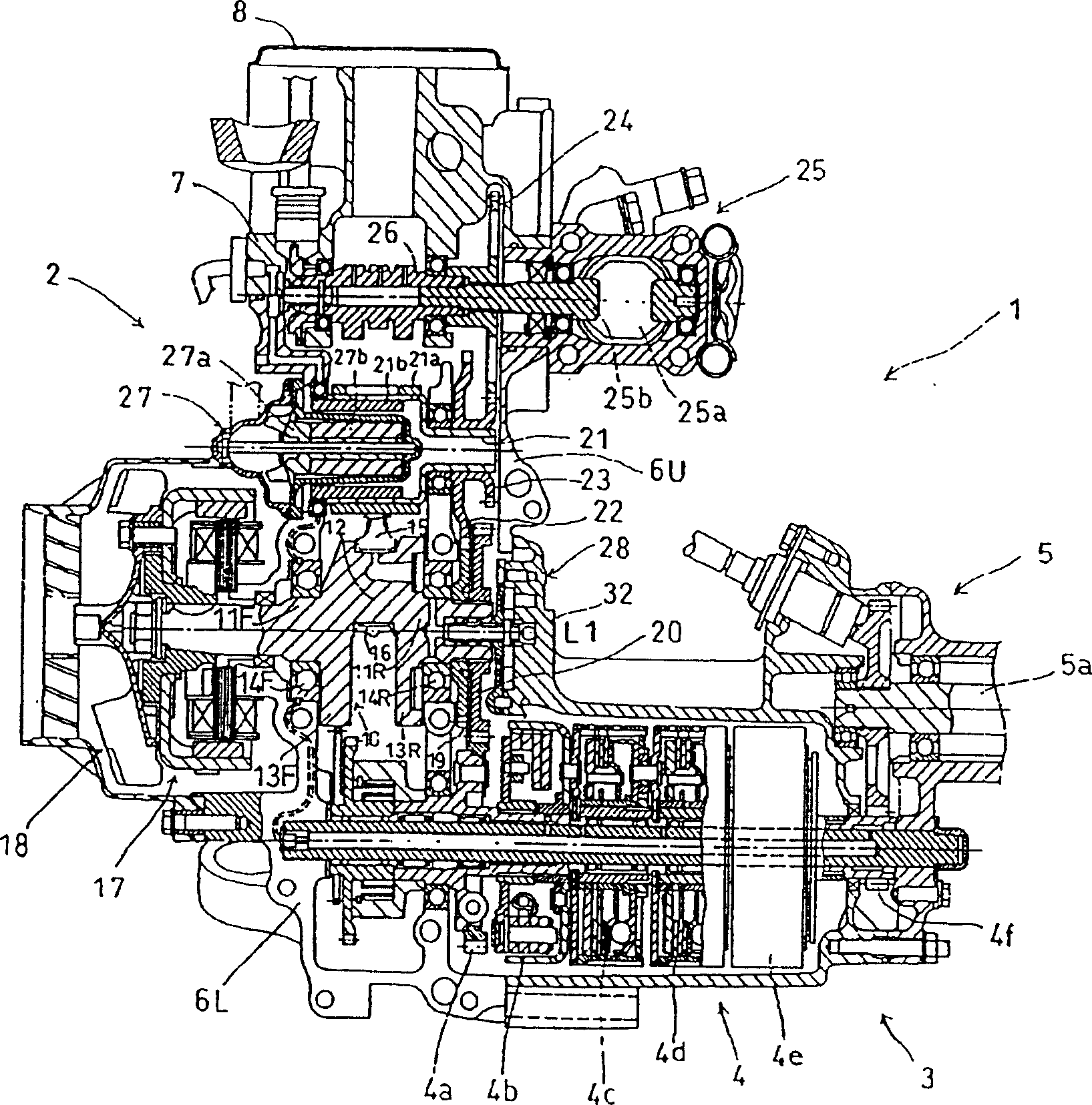
[0030] Below, refer to Figure 1 to Figure 11 , to illustrate an embodiment of the present invention.

[0031] Figure 1 to Figure 6 It is a figure explaining 1st Example. figure 1 It is a planar sectional view of a power unit equipped with an internal combustion engine 2 to which the crankshaft of the present invention is applied.

[0032] The power unit mounted on the two-wheeled motor vehicle is equipped with an internal combustion engine 2 and a power transmission device 3 . The power transmission device 3 has a planetary gear type transmission 4 and a final reduction device 5 . The internal combustion engine 2 is a spark ignition type 4-stroke single-cylinder water-cooled internal combustion engine. It is composed of crankcases 6U, 6L, cylinder head 7 and cylinder head cover 8 which are divided up and down. The cylinder 9 is integrally formed on the upper crankcase 6U. upper part (see figure 2 ).

[0033] The crankshaft 10 is integrally formed by a pair of front an...


PUM


Abstract

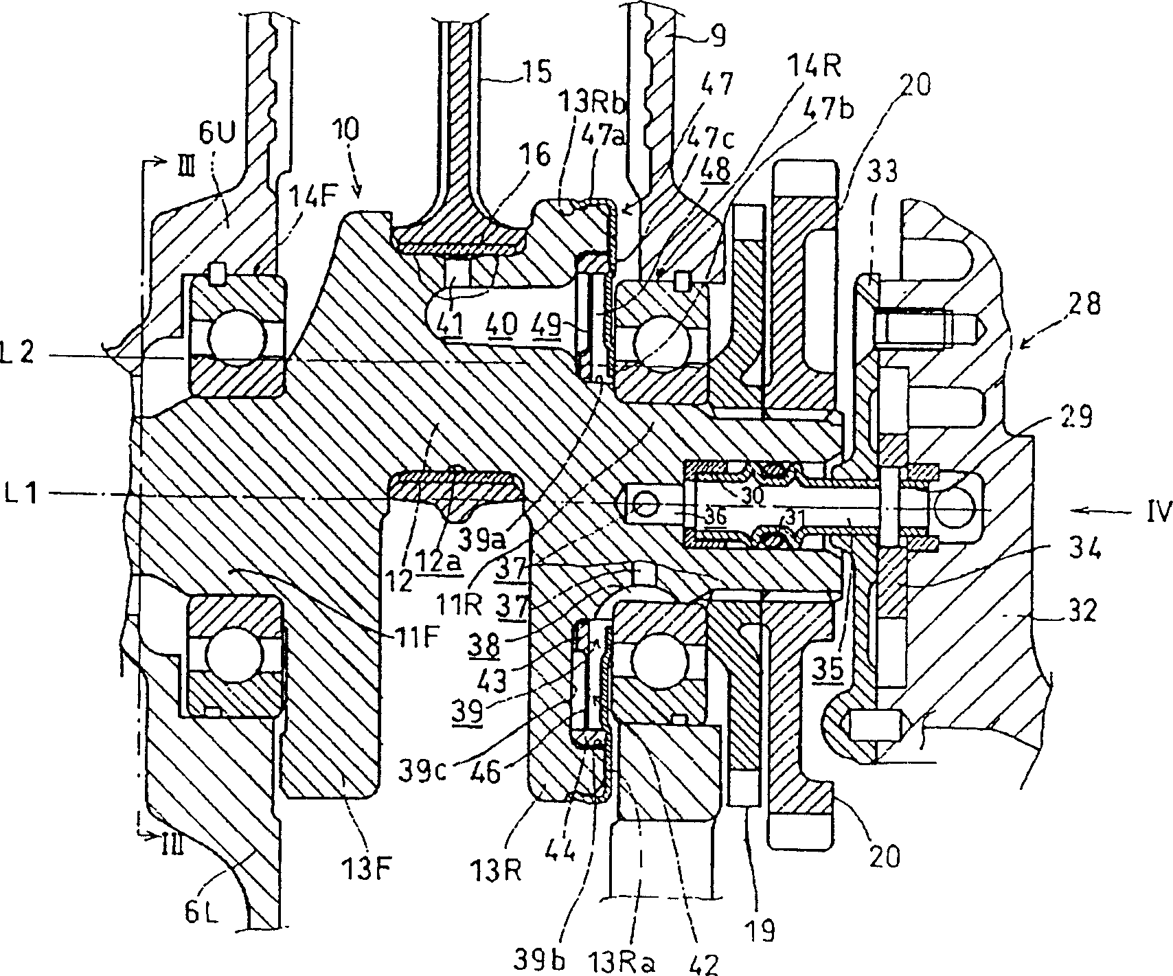
The present invention provides a crankshaft equipped with an oil filter 42 . By using an oil filter, foreign matter such as garbage can be separated well without increasing the size and weight of the crankshaft. On the crankshaft 10, the connecting rod 15 is connected to the crankpin 12 through the bearing 16, and an annular groove 39 is provided on the side surface 13Ra of the crankshaft counterweight 13R, and the annular groove 39 constitutes a channel for supplying lubricating oil to the bearing 16. An oil filter 42 is housed in the annular groove 39 as a part of the lubricating oil passage.

Description

technical field [0001] The present invention relates to a crankshaft provided with a lubricating oil passage for supplying lubricating oil to crank pins. Background technique [0002] In an internal combustion engine, the piston is connected to the crankshaft via a connecting rod in order to convert the reciprocating motion of the piston into the rotational motion of the crankshaft. At this time, the connecting rod is connected to the crank pin of the crankshaft through a bearing made of bearing alloy. The bearing forms a lubricating oil film with the help of lubricating oil, and keeps the metals in a non-contact state. It not only has a compact structure, but also has the advantages of low noise and high durability. [0003] However, if the lubricating oil supplied to the bearing contains solid foreign matter such as garbage, the durability of the bearing will be impaired and the frictional loss on the sliding surface will increase. For this reason, an oil filter is insta...

Claims


Application Information

Patent Timeline
Patent Type & Authority Patents(China)
IPC IPC(8): F01M11/03F16C3/14
Inventor 小笠原敦朝仓孝文
Owner HONDA MOTOR CO LTD
Learn More