
Method for monitoring radial gap between rotor and stator of electric generators and device for carrying out said method

A radial clearance and motor rotor technology, applied in the direction of adjusting/balancing rotors, electrical components, electromechanical devices, etc., can solve the problems of destroying generator downtime and not being able to provide forecasts of radial clearance real-time shape

Inactive Publication Date: 2005-03-09
SIEMENS AG
View PDF0 Cites 0 Cited by
  • Summary
  • Abstract
  • Description
  • Claims
  • Application Information

AI Technical Summary

Problems solved by technology

In extreme cases this can cause the rotor to brush against the stator while the generator is operating, with the result being severe damage and prolonged generator downtime
[0009] According to the traditional monitoring method for the radial gap between the generator rotor and the stator, it cannot provide a forecast for the real-time shape of the radial gap during the working process of the generator
The method of monitoring the vibration of the stator laminated core is usually used, but this method can only partially detect the change in the shape of the radial gap between the rotor and the stator

Method used


Image

  • Method for monitoring radial gap between rotor and stator of electric generators and device for carrying out said method
  • Method for monitoring radial gap between rotor and stator of electric generators and device for carrying out said method
  • Method for monitoring radial gap between rotor and stator of electric generators and device for carrying out said method

Examples


Embodiment Construction

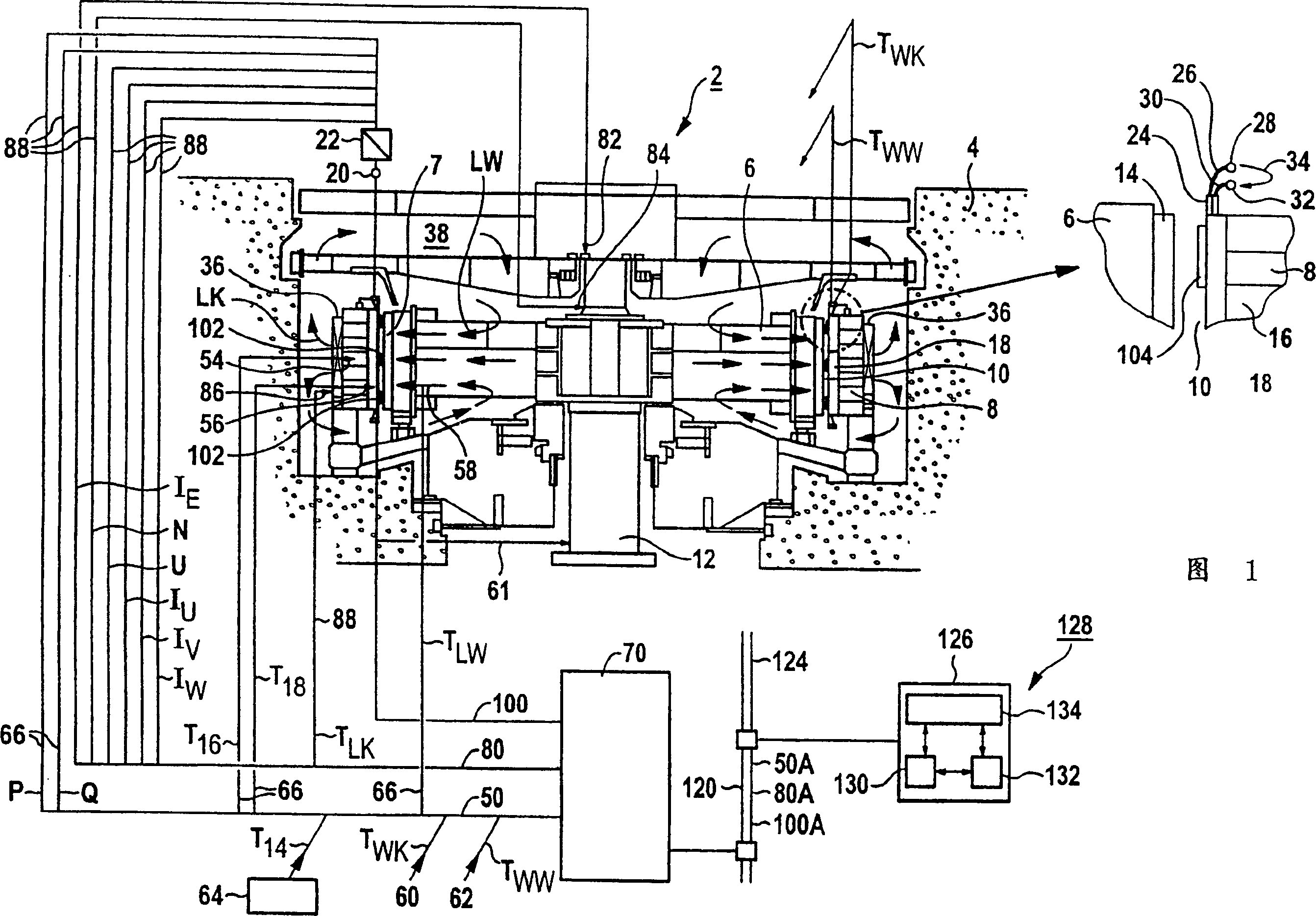
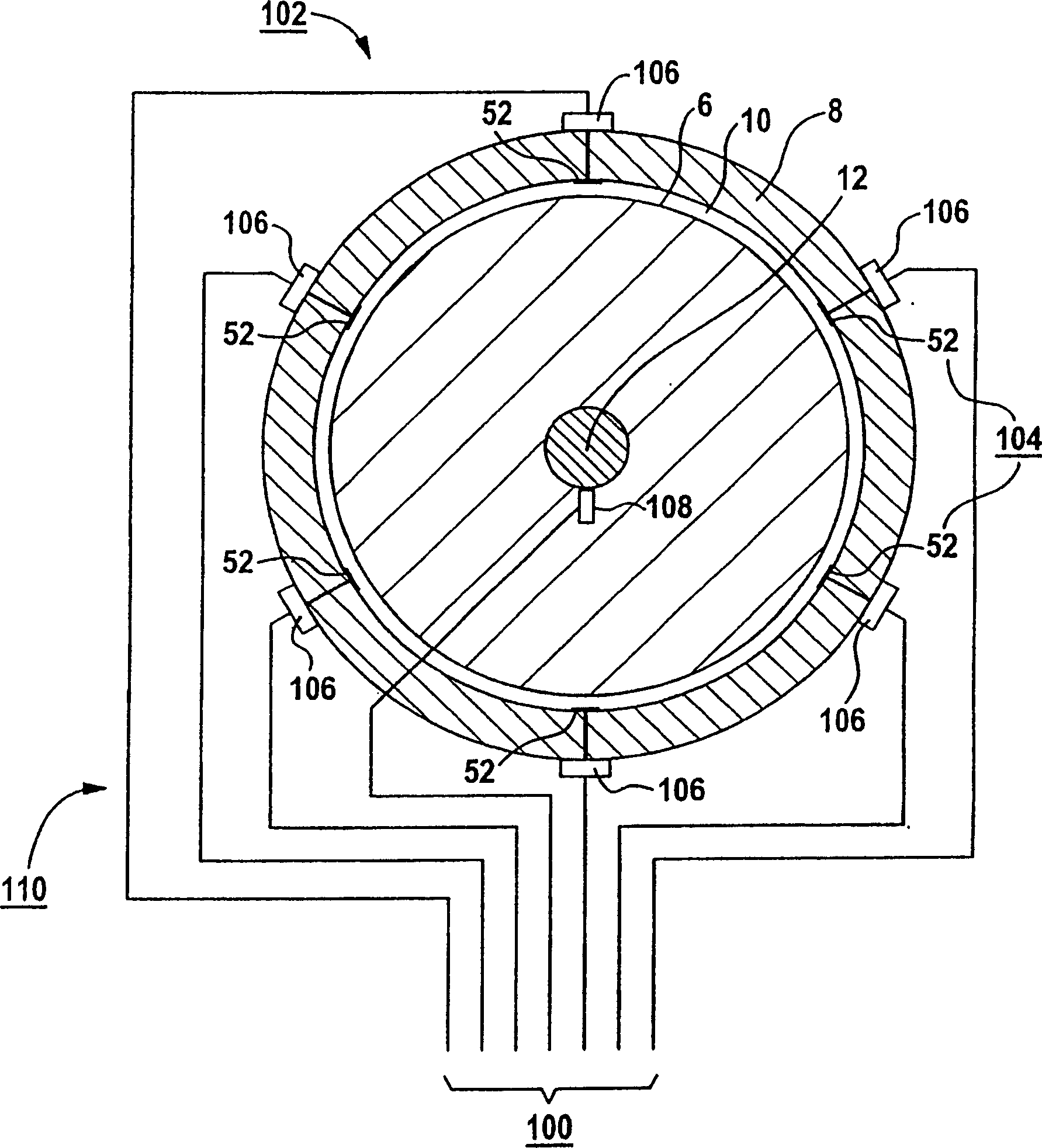
[0116] The generator 2 shown schematically in longitudinal section in FIG. 1 is designed as a hydroelectric generator and includes a rotor 6 in a housing 4 which is surrounded concentrically by a stator 8 . The rotor 6 and the stator 8 are separated from each other by a radial gap 10 . The rotor 6 includes a shaft 12, a shaft 12 for generating the excitation current I of the rotor 6 E The winding 14 and many poles not shown in detail in the figure. The stator 8 has a laminated core 16 and a winding 18 . The winding 18 of the stator 8 is connected via terminals 20 to an isolating amplifier 22 connected to a measuring circuit, which is not shown in the figure.

[0117] The winding 18 of the stator 8 comprises three separate windings U, V and W, which are not shown in this figure. The three separate windings U, V and W in turn comprise winding bars 24 connected in electrical series, only some of which are shown in the figure. When the generator 2 is in operation, cooling wate...


PUM


Abstract

The invention relates to a method for monitoring the radial gap (10) between the rotor (6) and the stator (8) of an electric generator (2). The aim of the invention is to provide a method that allows an especially reliable analysis of the shape of the radial gap (10) during operation of the generator (2). To this end, a measuring cycle is carried out in the stationary and balanced operating mode of the generator at defined intervals. In every measuring cycle, current parameters (120) of the radial gap (10) are determined from current marginal values (50) of the generator (2), from current influential values (80) of the generator (2) and from current measuring data (100). These parameters are used to determine and evaluate the shape of the radial gap (10) and the distance between the rotor (6) and the stator (8) by comparing them with reference parameters. The inventive method allows to better predict when repairs have to be made.

Description

technical field [0001] The invention relates to a method for monitoring the radial gap between the motor rotor and the stator. It also relates to a device for implementing the method. Background technique [0002] The radial gap between the generator rotor and the stator has the shape of a concentric annular cylinder. Here, the outer surface is formed by the laminated core of the stator, and the inner surface is formed by the surface of the upper pole of the rotor, which determines the maximum rotor diameter. [0003] The size of the radial gap, which is decisive for the magnetic field or required excitation, is generally small relative to the diameter of the stator inner wall, for example in a generator with a rotor diameter of 16 m it is approximately 0.2% of the stator inner wall diameter. Via the radial gap, a magnetic interaction takes place between the rotor and the stator. In this case, this magnetic force increases the existing static and / or rotational asymmetry, ...

Claims


Application Information

Patent Timeline
Patent Type & Authority Patents(China)
IPC IPC(8): H02K11/00H02K11/20H02K11/25H02K11/35H02K15/16
CPCH02K15/16H02K11/0047H02K11/001H02K11/0078H02K11/20H02K11/25H02K11/35
Inventor 赫曼·谢尔迪特尔·布赖恩德尔
Owner SIEMENS AG
Learn More