Magnetic head and its mfg. method and magnetic recordig and/or reproducing system

A technology of magnetic recording and magnetic head, applied in the direction of magnetic recording, magnetic recording head, data recording, etc., can solve the problems such as the reduction of recording and reproduction efficiency and the limitation of improving the efficiency of magnetic head.

Inactive Publication Date: 2005-02-23
KK TOSHIBA
View PDF1 Cites 0 Cited by
  • Summary
  • Abstract
  • Description
  • Claims
  • Application Information

AI Technical Summary

Problems solved by technology

Therefore, even if a small magnetic circuit is to be formed, there is a limit to the improvement of the efficiency of the magnetic head.
In addition, even if the desired magnetic head is obtained with a low yield, there is a problem that the recording and reproduction efficiency at shorter wavelengths is greatly reduced, making it impossible to perform recording / reproduction at a high density

Method used


Image

  • Magnetic head and its mfg. method and magnetic recordig and/or reproducing system
  • Magnetic head and its mfg. method and magnetic recordig and/or reproducing system
  • Magnetic head and its mfg. method and magnetic recordig and/or reproducing system

Examples


Embodiment Construction

[0060] (first preferred embodiment)

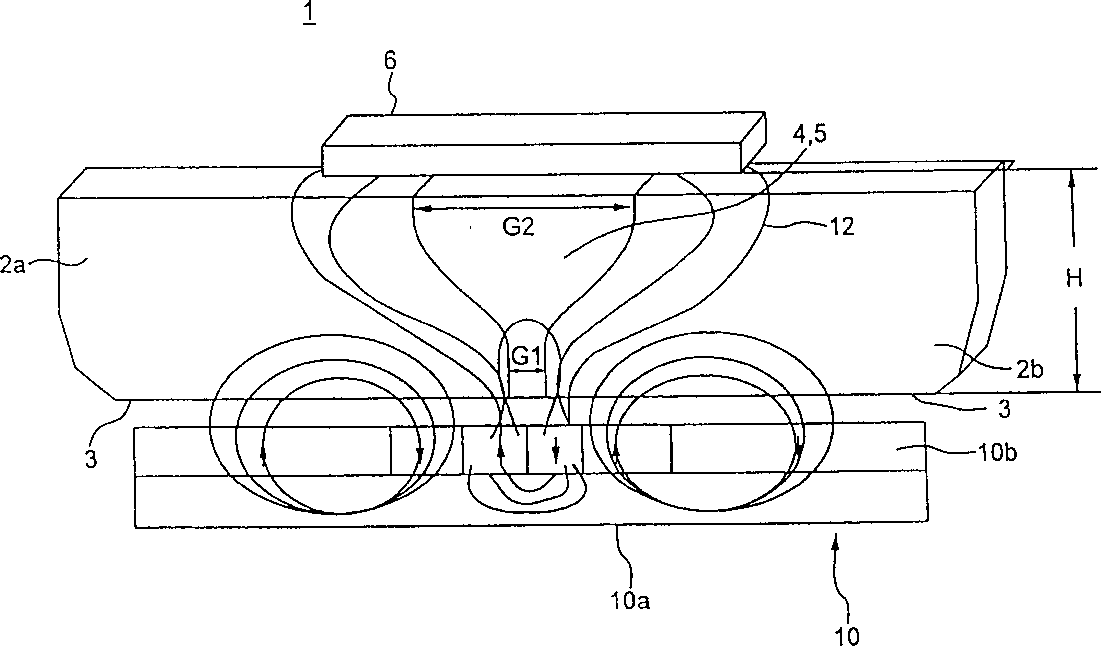
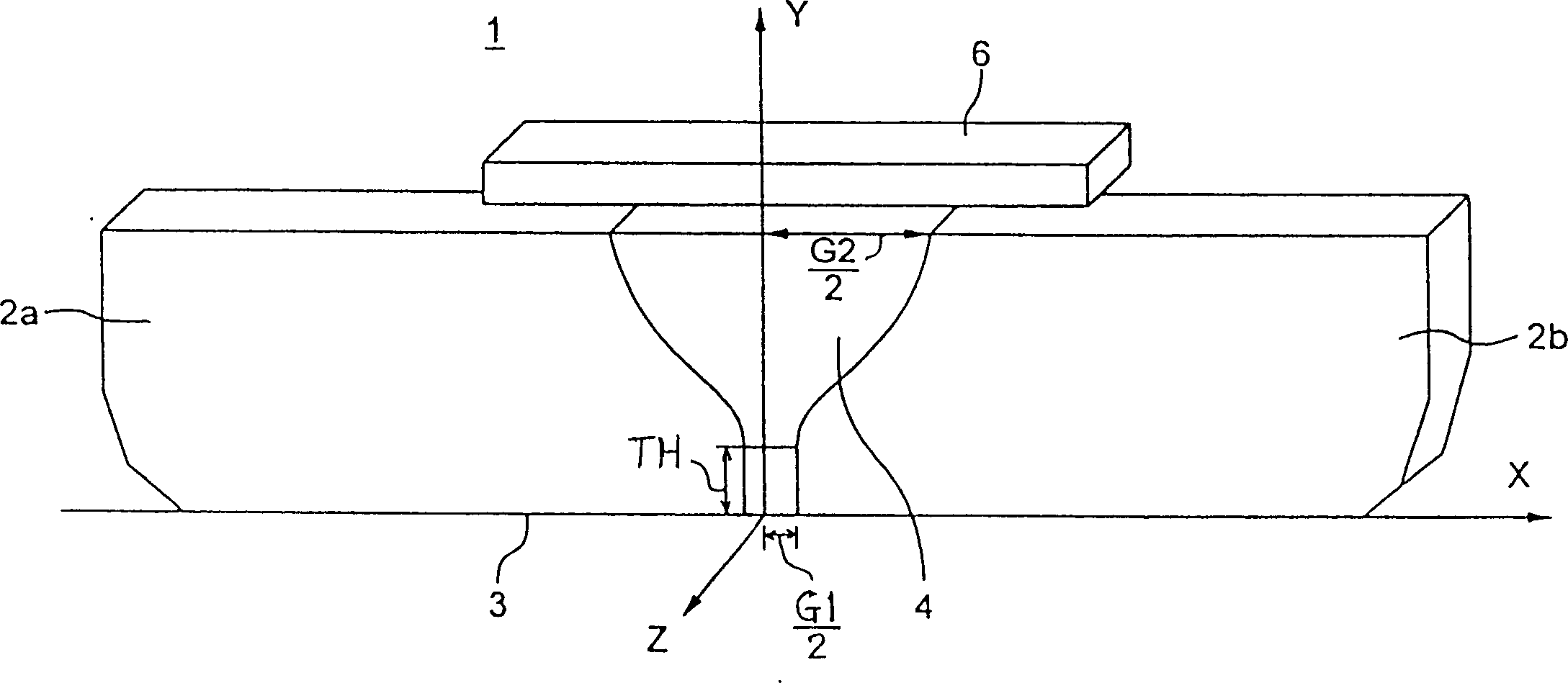
[0061] exist figure 1 The structure of the first preferred embodiment of the magnetic head according to the present invention is shown in . The magnetic head 1 in the first preferred embodiment includes a pair of magnetic parts 2a and 2b made of a soft magnetic material having a thickness of eg about 200nm, a recording coil 5, and a magnetoresistance effect element 6 of eg 300nm2. The principal planes 3 of the pair of magnetic parts 2 a and 2 b are arranged parallel to the recording medium 10 . That is, the main plane 3 serves as a medium-facing surface. In addition, the recording medium 10 is a longitudinal recording medium formed such that a signal-recorded medium layer 10b is formed on a soft magnetic material thin film 10a.

[0062] The pair of magnetic parts 2a and 2b are designed to be separated from each other by a magnetic gap 4 . The magnetic gap 4 is configured to have a relatively small length G1 of, for example, about 50 n...


PUM

PropertyMeasurementUnit
thicknessaaaaaaaaaa

Abstract

The present invention provides a magnetic head, which performs highly efficient recording / reproducing even when a magnetic path length is shortened, and a signal wavelength is short. This magnetic head is provided with magnetic body parts and made of a pair of soft magnetic materials, in which main surfaces face a recording medium, and a magnetic gap, in which a gap between the pair of magnetic body parts in a side opposite the main surface is wider than that in the main surface, and continuously changed from the main surface side to the side opposite the main surface.

Description

[0001] This application claims priority from Japanese Patent Application No. 2000-95082 filed on March 30, 2000, the entire contents of which are hereby incorporated by reference. technical field [0002] The present invention generally relates to a magnetic head, a method of manufacturing the same, and a magnetic recording and / or reproducing system. Background technique [0003] It is well known that the efficiency of a magnetic head increases rapidly as the length of the magnetic path of the magnetic circuit decreases. For example, if Figure 18A It is shown that the efficiency increases rapidly as the magnetic path length is reduced to 2 μm (=2000 nm) or less. like Figure 18B As shown in , the magnetic path length means the magnetic part 52a, the magnetic part 53a, the magnetoresistance effect element (such as GMR (giant magnetoresistance effect) element), the magnetic part 53b and the magnetic part through a magnetic head. The length of the magnetic circuit of the por...

Claims


Application Information

Patent Timeline
Patent Type & Authority Patents(China)
IPC IPC(8): G11B5/00G11B5/127G11B5/187G11B5/23G11B5/31G11B5/39
CPCG11B5/3116G11B5/3925G11B2005/0021G11B2005/0002G11B5/127G11B5/00G11B5/1278Y10T29/49039Y10T29/49043Y10T29/49044Y10T29/49046Y10T29/49055Y10T29/49067G11B5/39
Inventor 與田博明大泽裕一船山知己
Owner KK TOSHIBA
Why Eureka
Try Eureka