
Button switch

A switch and button technology, applied in the structural field of small button switches, can solve the problems of contact position change, cover deformation, melting around fixed contacts, etc., to increase the distance along the surface, reduce the rise of flux, reduce the change of contact position or The effect of cylindrical deformation

Inactive Publication Date: 2005-02-02
ALPS ALPINE CO LTD
View PDF0 Cites 0 Cited by
  • Summary
  • Abstract
  • Description
  • Claims
  • Application Information

AI Technical Summary

Problems solved by technology

However, there is a problem that the wall thickness of the housing 11 under the terminal part is thinned, and the fluidity of the resin is not good during molding, so it cannot be molded.
[0018] And, when the switch is soldered, there may be such a problem: the heat added to the above-mentioned external terminals 13a, 13b is transmitted to the terminal parts, and is easily added to the above-mentioned central fixed contact 12a and the surrounding fixed contacts 12b, making the surrounding fixed contacts Melting, changing the contact position, or deforming the cover plate 15

Method used


Image

  • Button switch
  • Button switch
  • Button switch

Examples


Embodiment Construction

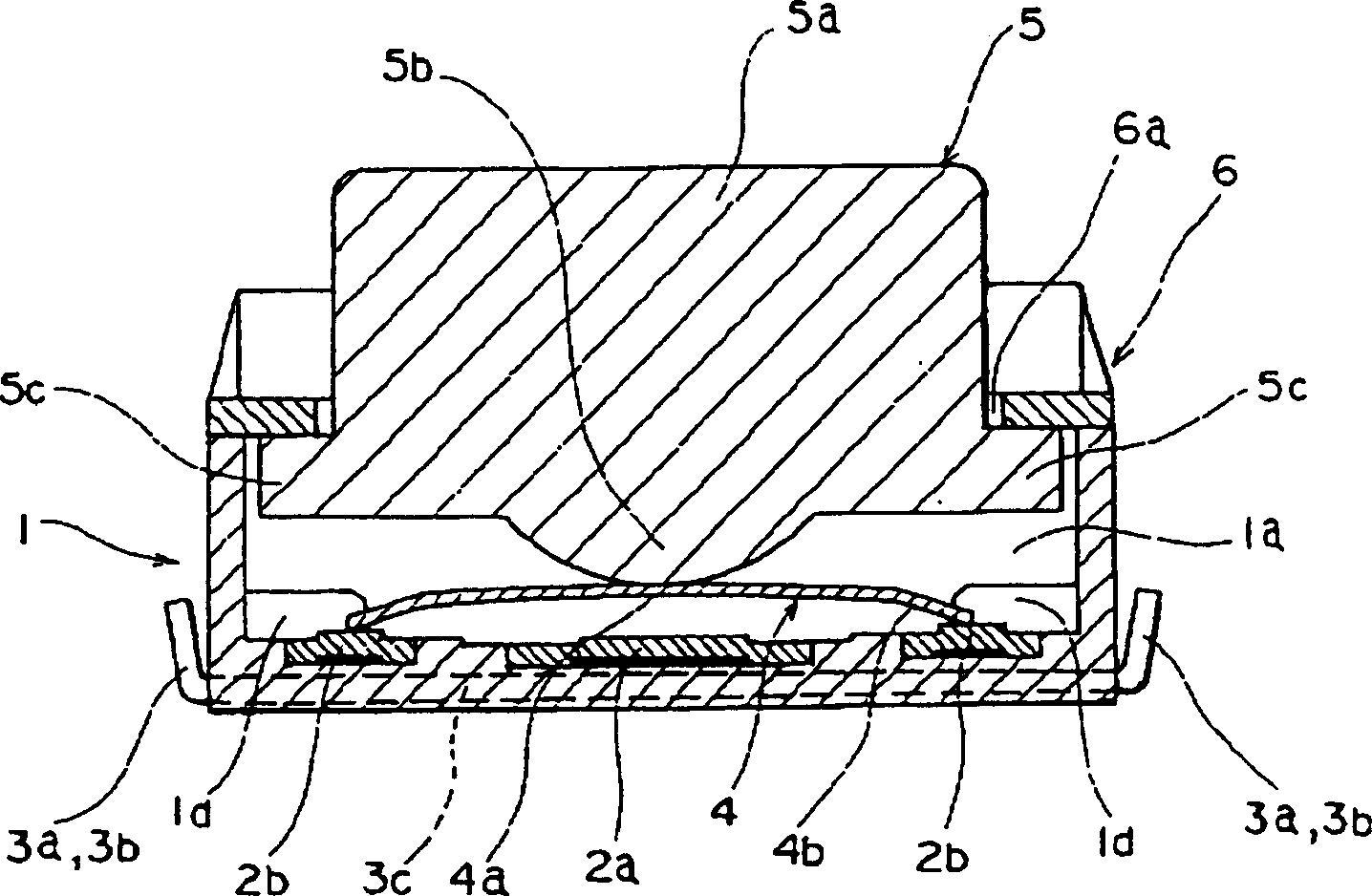
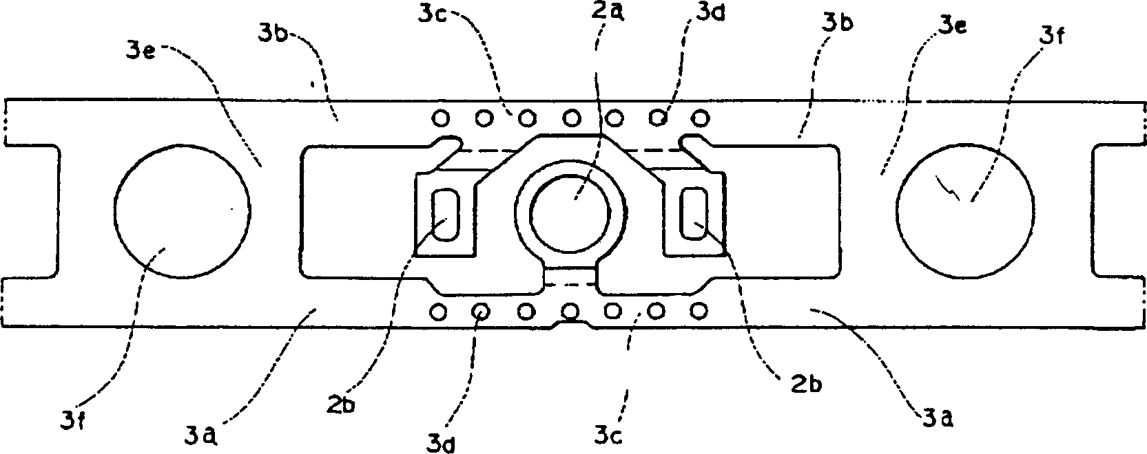
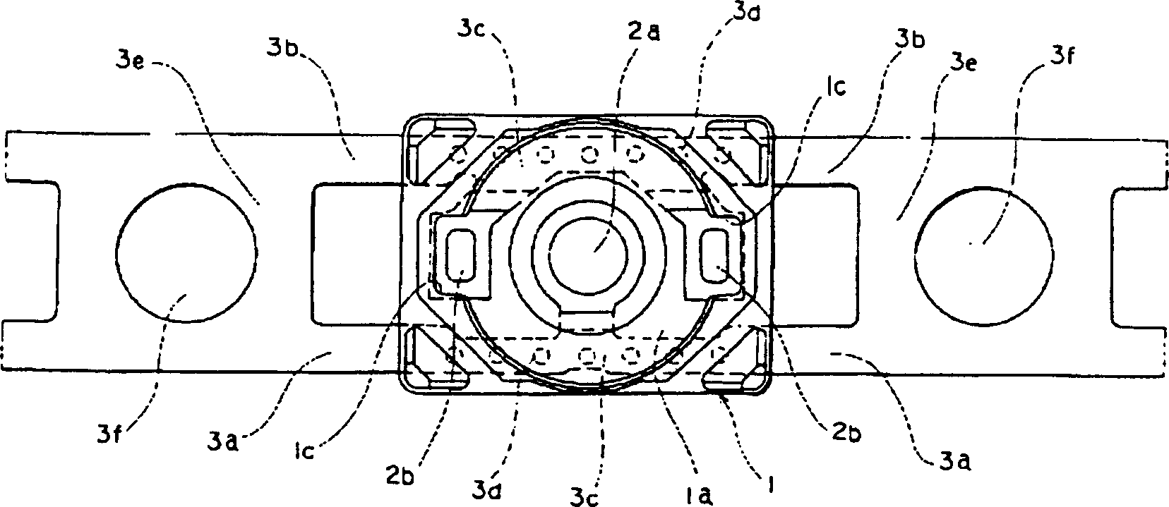
[0047] The push button switch embodiment of the present invention is shown in the following Figure 1 to Figure 4 .

[0048] In the figure, the casing 1 is made of insulating material such as synthetic resin to form a square box shape, which is square in shape, has an opening on the top, and has a housing portion 1a inside. A central fixed contact 2a made of a conductive metal terminal member is provided at the center of the inner bottom surface of the housing portion 1a of the housing 1 so that it protrudes from the terminal member, and the upper side is exposed, and the central fixed contact 2a On the positions where the two sides of the two sides face each other, a peripheral fixed contact 2b, 2b similarly made of a conductive metal terminal member is provided, protruding from the terminal member, and the upper side is exposed. Further, external terminals 3a, 3b protruding outward are formed on opposing outer surfaces of the housing 1 .

[0049] The external terminals 3a,...


PUM


Abstract

The present invent provides a structure of a push-button switch wherein reduction of material can be obtained through reduction of a material width by changing the bonding bar of a hoop-shaped terminal material into an inner bar and wherein influences of heat and flux at the time of soldering can be reduced. This switch is provided with a resin made housing 1 having a housing part 1a, fixed contact points 2a, 2b wherein a flat metal terminal material is embedded in the bottom part of the housing 1 and wherein one part is protruded and formed in an inner-bottom face of the housing part 1a, a movable contact point 4 capable of contacting and separating from these fixed contact points 2a, 2b, and outer terminals 3a, 3b jointed in succession with the fixed contact points 2a, 2b and led out outward from the side face of the housing 1. A through hole 3d is formed in the terminal material, the terminal material is embedded in the bottom part of the housing 1 by communicating with the resin of the top and bottom faces via this through hole 3d, and the outer terminals 3a, 3b are led out from the side face of the housing 1 onto the same plane as the embedded terminal material.

Description

technical field [0001] The present invention relates to a push button switch which turns the dome-shaped movable contact in reverse by pressing, especially relates to the structure of the small push button switch used in portable electronic equipment and the like. Background technique [0002] The structure of the past pushbutton switch is shown in Figure 5-7 . Figure 5 is the profile view of the button switch; Figure 6 7 is a plan view of the ring-shaped terminal member; 7 is a plan view of the state in which the ring-shaped terminal member is buried in the case. [0003] The past button switch, its components are: [0004] a square housing 11, which has a housing; [0005] a central fixed contact 12a and peripheral fixed contacts 12b, which are arranged in the housing portion of the housing 11; [0006] External terminals 13a, 13b, which are connected to the central fixed contact 12a and the surrounding fixed contacts 12b, are drawn out from the side of the housing ...

Claims


Application Information

Patent Timeline
Patent Type & Authority Patents(China)
IPC IPC(8): H01H13/04H01H9/02H01H11/00H01H13/52
Inventor 佐藤秀隆贺川和义
Owner ALPS ALPINE CO LTD
Learn More