
Digital video frequency recording equipment

A technology of digital video recording and video recording, applied in the direction of digital recording/reproduction, data recording, magnetic recording, etc.

Inactive Publication Date: 2005-01-26
PANASONIC CORP
View PDF0 Cites 0 Cited by
  • Summary
  • Abstract
  • Description
  • Claims
  • Application Information

AI Technical Summary

Problems solved by technology

There are no measures taken against this noise in the prior art

Method used


Image

  • Digital video frequency recording equipment
  • Digital video frequency recording equipment
  • Digital video frequency recording equipment

Examples


Embodiment 1

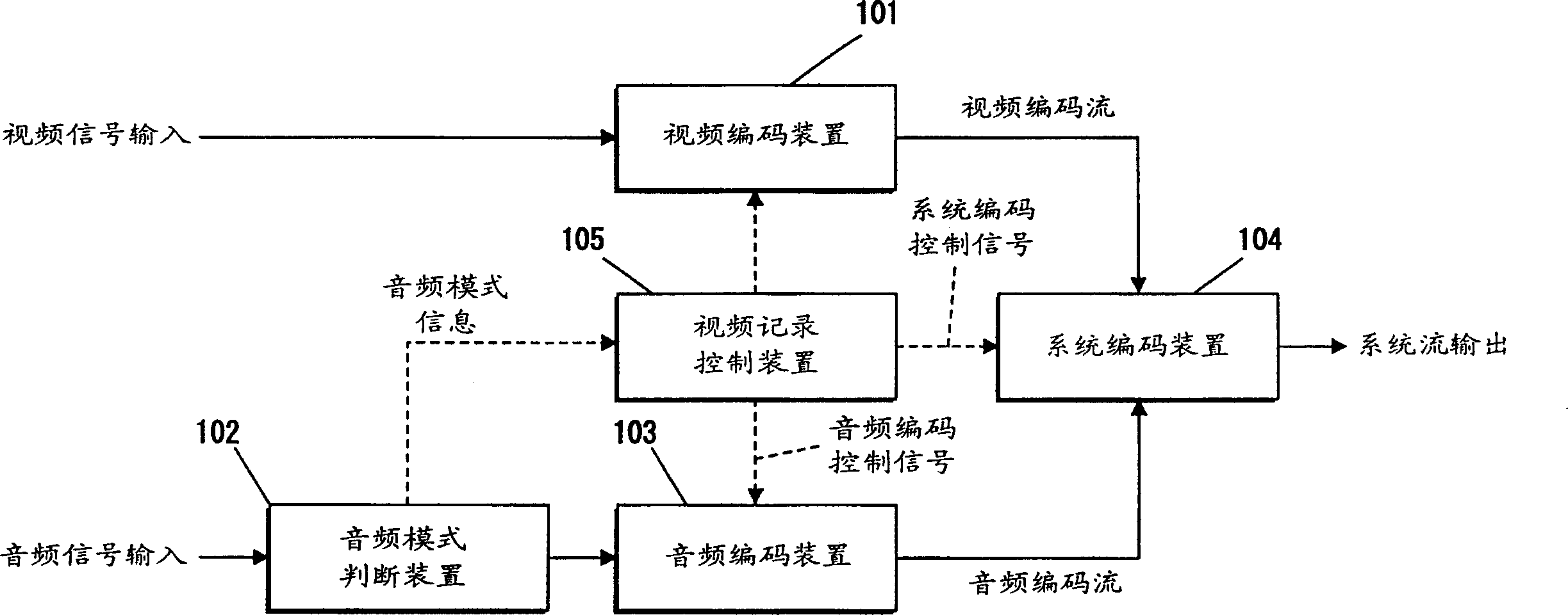
[0018] First, a first embodiment of the present invention will be described. figure 1 is a block diagram of the digital video recording apparatus according to the first embodiment of the present invention.

[0019] exist figure 1 , the video encoding device 101 compresses and encodes an input video signal. The audio mode judging means 102 determines the audio mode of the audio signal input.

[0020] The audio encoding means 103 encodes an input audio signal. The system encoding means 104 multiplexes the encoded video encoded stream and the encoded audio encoded stream, and generates a system stream. Video recording control means 105 controls start of video recording, stop of video recording, temporary stop of video recording, and release of temporary stop of video recording by video encoding means 101 , audio encoding means 103 , and system encoding means 104 .

[0021] In the digital video recording apparatus constructed as described above, the video recording control m...

Embodiment 2

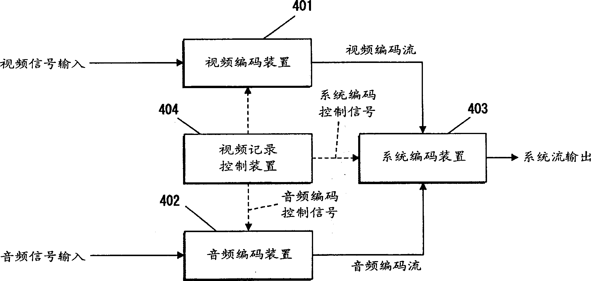
[0028] Next, a second embodiment of the present invention will be described. image 3 is a block diagram of a digital video recording apparatus according to a second embodiment of the present invention.

[0029] exist image 3 , the video encoding device 401 compresses and encodes an input video signal. Audio encoding means 402 encodes an input audio signal.

[0030] The system encoding means 403 multiplexes the encoded video encoded stream and the encoded audio encoded stream and generates a system stream. Video recording control means 404 controls start of video recording, stop of video recording, temporary stop of video recording, and release of temporary stop of video recording by video encoding means 401 , audio encoding means 402 and system encoding means 403 .

[0031] In the digital video recording apparatus constructed as described above, the video recording control means 404 controls the audio encoding means 402 so that when determined by the audio encoding condit...


PUM


Abstract

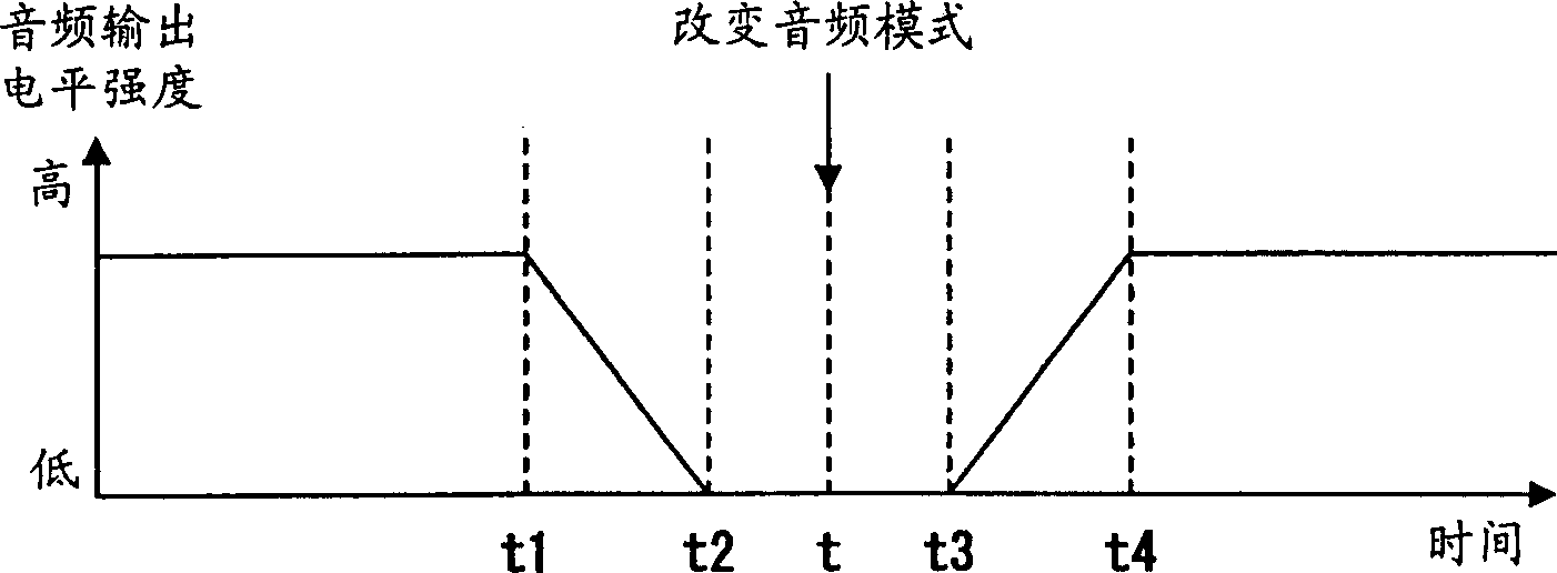
To obtain a digital recorder in which noise appearing in a reproduced sound is suppressed when audio encoding conditions (stereo / monoral) are altered. The digital recorder comprises a video encoding means , an audio mode decision means , an audio encoding means , a system encoding means for multiplexing an encoded video / audio, and a recording control means 105. When audio information is varied, the recording control means varies the audio encode mode after lowering the audio output level gradually and then increases the audio output level gradually again.

Description

technical field [0001] The present invention relates to an audio encoding control technique used when an audio encoding condition of a digital video recording apparatus that digitally encodes a video signal and an audio signal changes. Background technique [0002] In recent years, with the expansion of the storage capacity of optical disks or hard disks, digital video recording apparatuses that digitally encode and store video signals and audio signals have come into practical use. [0003] Audio signals can be classified into stereo (two channels), monaural (monaural) and multiplexed (primary voice: one channel + secondary voice: one channel) sound signals. Also, in the Dolby AC-3 or Linear PCM standard, there are 5.1 channels of audio signals. In the digital audio stream, the picture / sound recording time can be controlled, or the sound quality at the time of reproduction can be controlled by changing the encoding bit rate. [0004] Figure 4 Shows changes in audio outpu...

Claims


Application Information

Patent Timeline
Patent Type & Authority Patents(China)
IPC IPC(8): H04N5/91G10L19/00G11B19/02G11B20/10G11B27/22H04N5/60H04N5/926
CPCH04N5/602G11B27/22G11B20/10009G11B2220/20G11B20/10H04N5/9267G11B19/02G11B2020/10537
Inventor 岩崎史朗中村和彦福田秀树川崎弘二郎
Owner PANASONIC CORP
Learn More