
Double frequency function curved antenna

A zigzag, antenna technology, applied in the directions of antennas, resonant antennas, antenna supports/installation devices, etc., can solve the problems of complex structure, troublesome production procedures, and enlarged zigzag conductors, so as to reduce the volume of the antenna and improve the design margin. high-quality, easy-to-manufacture effects

Inactive Publication Date: 2004-12-15
BENQ CORP
View PDF1 Cites 1 Cited by
  • Summary
  • Abstract
  • Description
  • Claims
  • Application Information

AI Technical Summary

Problems solved by technology

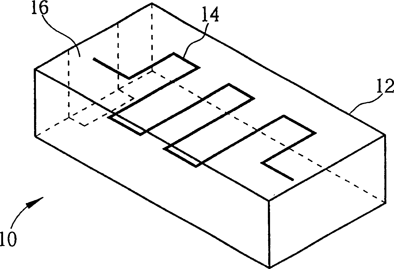
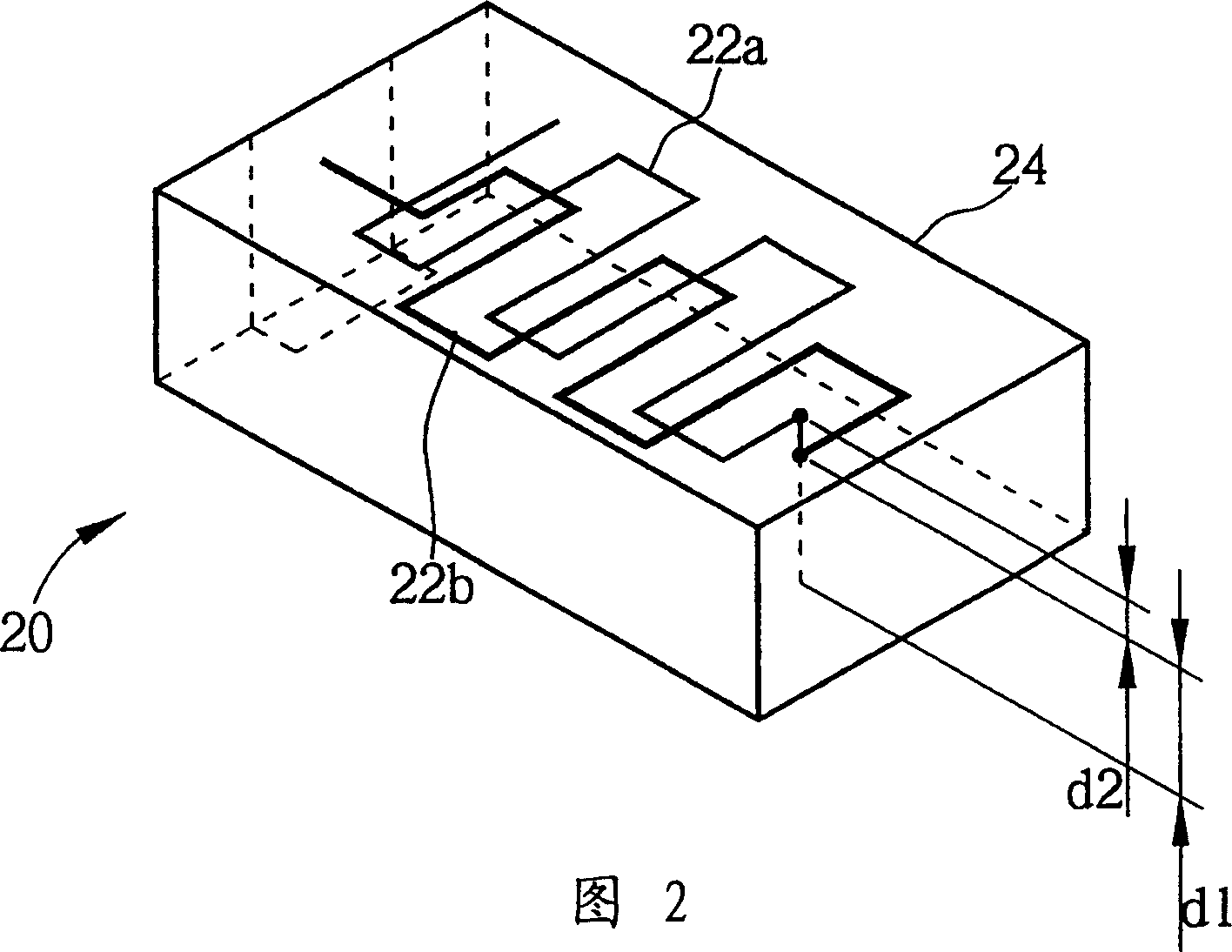
[0006] However, the dual-band microstrip meander antenna 20 shown in FIG. 2 still has its disadvantages
First of all, this kind of antenna has meandering conductors 22a, 22b arranged in different layers, the structure is complicated, and the manufacturing process is cumbersome.
Furthermore, when designing an antenna, the conductor used to receive electromagnetic waves should not be too close to the high-frequency circuit of the system, otherwise it will interfere with the normal operation of the high-frequency circuit. Therefore, the distance d1 shown in Figure 2 should not be too small. It adopts a layered structure, so the distance d2 cannot be too small, so the volume of the entire antenna cannot be further reduced
[0007] In addition, the lower the frequency of the electromagnetic wave, the longer the wavelength, and the receiving antenna must be correspondingly lengthened. Therefore, under the structure shown in FIG. , which will increase the size of the antenna, which does not conform to the design trend of thinner and shorter communication devices

Method used


Image

  • Double frequency function curved antenna
  • Double frequency function curved antenna
  • Double frequency function curved antenna

Examples


Embodiment Construction

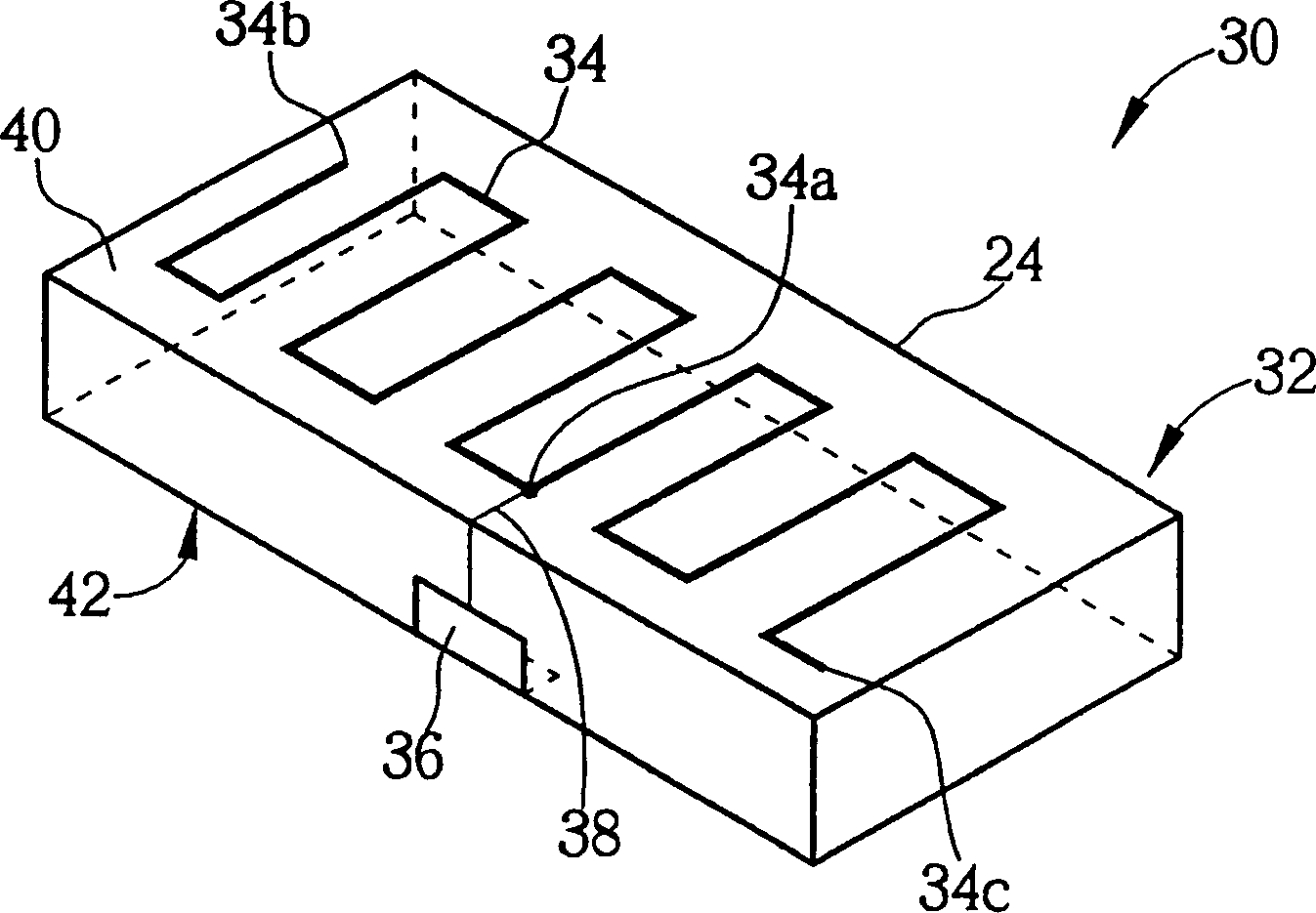
[0022] see image 3 , image 3 It is a schematic diagram of the microstrip meander antenna 30 according to the first embodiment of the present invention. The microstrip meander antenna 30 includes a substrate 32 , a meander-shaped conductor 34 , a feeding terminal 36 and a feeding line 38 . The substrate 32 is formed of a dielectric material or a magnetic material, and includes a first surface 40 . The meandering conductor 34 is attached to the first surface 40 in a manner of periodically reciprocating bending, which includes a middle junction 34a located between two ends 34b, 34c of the meandering conductor 34 . Part of the feed-in line 38 is attached to the first surface 40, and is electrically connected to the feed-in end 36 and the intermediate contact 34a, and is used to transmit the radio signal received by the meander conductor 34 to a wireless communication device (such as a mobile phone), Or apply a voltage to the meander conductor 34 to transmit the radio signal g...


PUM


Abstract

A double frequency antenna in zigzag shape, which can provide antenna receiving and transmitting functions for radio communication device, includes base plate, conductor in zigzag shape and a feeder line, among which the base plate is made of dielectric material or magnetic material and including a first surface, the conductor in zigzag shape is attached on the first surface with a periodic reciprocating folding mode and including a middle jointing point between two ends of the conductor in zigzag shape, the feeder line electrically connected with the jointing point in the said middle joint is used for transmitting radio signal to the radio communication device or transmitting the radio signal created by radio communication device to the outside via the conductor in zigzag shape.

Description

technical field [0001] The invention relates to a microstrip meandering-line antenna (Microstrip Meandering-Line Antenna), in particular to a microstrip meandering-line antenna with a dual-band (Dual-Band) function. Background technique [0002] With the development of wireless communication technology, the design of the antenna is also very important. Therefore, how to design a dual-band antenna suitable for different frequency bands has become an important issue in today's antenna design. The antennas used in traditional wireless communication equipment are mostly monopole antennas (Monopole Antenna) or helical antennas (Helix Antenna) with 1 / 4 wavelength. However, due to the large volume occupied, the aesthetics and integrity of the product are affected It is not easy to integrate with the circuit board or the case, so it has been gradually replaced by other types of antennas. [0003] Currently, there are three types of antennas that are mainly used in mobile communicat...

Claims


Application Information

Patent Timeline
IPC IPC(8): H01Q1/24H01Q1/38H01Q5/00H01Q9/42
Inventor 王健仁
Owner BENQ CORP
Learn More