Undersensor magnetic suspension rotor system

A magnetic levitation rotor and sensor technology, used in bearings, shafts and bearings, control using feedback, etc., can solve problems such as excessive heating, extra noise, lubricating fluid pollution, and wear

Inactive Publication Date: 2004-12-15
WUHAN UNIV OF TECH
View PDF0 Cites 0 Cited by
  • Summary
  • Abstract
  • Description
  • Claims
  • Application Information

AI Technical Summary

Problems solved by technology

[0006] However, the increase in the speed of the mechanical system will lead to problems such as excessive heat generation, wear, vibration, extra noise, and lubricant pollution. Traditional bearings are difficult to meet the requirements of the increased speed of hard disk and optical disk rotors.

Method used


Image

  • Undersensor magnetic suspension rotor system
  • Undersensor magnetic suspension rotor system
  • Undersensor magnetic suspension rotor system

Examples


Embodiment approach

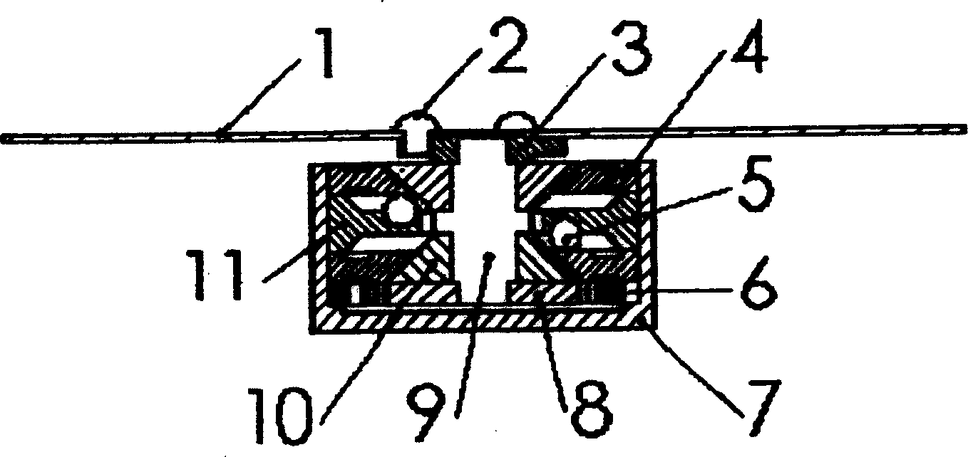
[0021] The principle diagram of the rotor structure of the under-sensor magnetic levitation (hard disk structure 2) of the present invention is as follows Figure 5 As shown, it is the second embodiment of the present invention, the hard disk platter 1 is connected with the housing 7 by screws 2 .

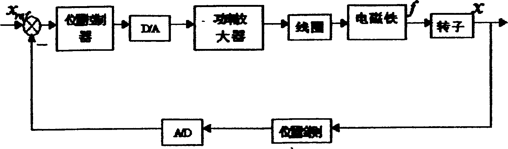
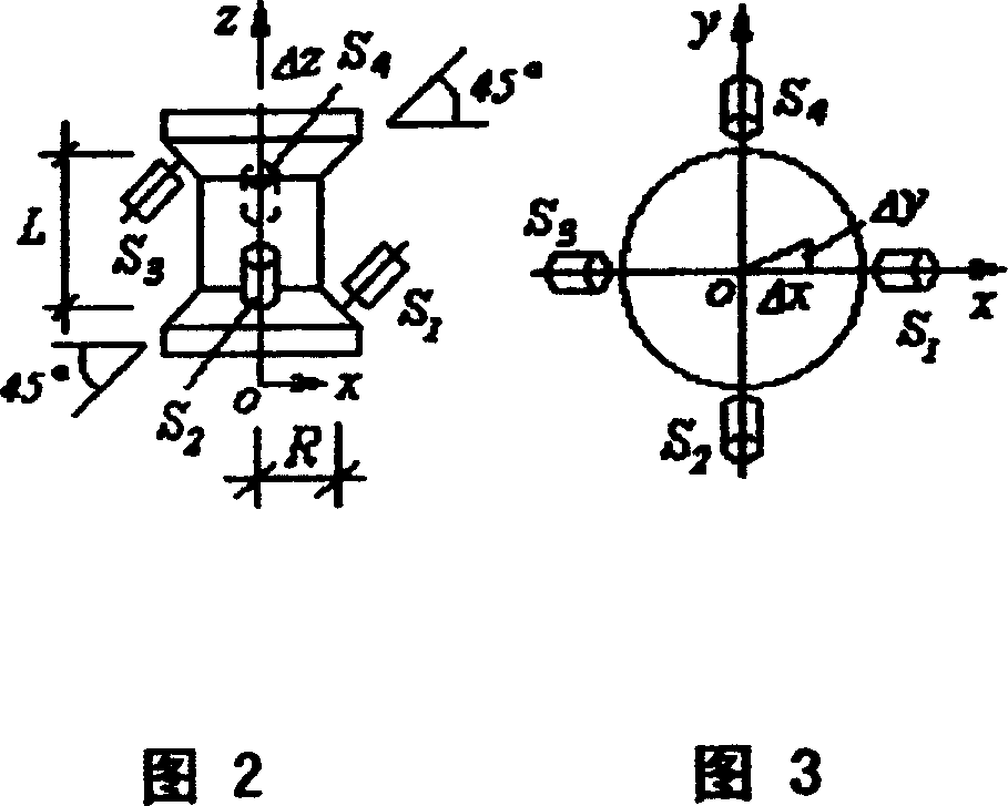
[0022] Under-sensor magnetic levitation rotor system, including rotor 9, motor rotor 8, housing 7, motor stator 6, A / D, DSP, D / A and its power amplifier, housing 7 is equipped with motor stator 6, sensor bracket 11 and 2 A tapered magnetic bearing stator 4; the rotor 9 is covered with two conical disks 10, and the two tapered magnetic bearing stators 4 are respectively located above and below the rotor 9; the sensor bracket 11 is located between the two tapered magnetic bearing stators 4, and the sensor bracket 11 is installed There are 4 sensors 5, represented by S1, S2, S3, S4 respectively, and the 4 sensors are 90° to each other on the horizontal projection plane, wherein the ax...


PUM


Abstract

The invention refers to an undersensor magnetic suspended rotor system, including the rotor, the electric machine rotor, the shell, the electric machine stator, A / D, DSP, D / A and the power amplifier. Its character: the coat of the rotor has two awl-shaped trays, two taper magnetic force bearing stators respectively are lied above and below the rotor; there are 4 sensors installed on the bracket of the sensor, and the awl-shaped tray and the taper magnetic force bearing stator compose the magnetic force bearing pair. It is also applied to other small magnetic suspended rotor systems with compact space construction.

Description

technical field [0001] The invention relates to a magnetic levitation rotor system, in particular to an under-sensor magnetic levitation rotor system. Background technique [0002] Considering the maglev rotor system from the perspective of mechanical principles, it is necessary to limit its 5 degrees of freedom to support a rotating spindle, so the general maglev rotor system requires 5 displacement sensors, that is, one degree of freedom requires one sensor. This measurement and control scheme with one displacement sensor for each degree of freedom can be defined as: "full sensor system". [0003] In practical applications, in order to reduce mechanical coupling and other reasons, a differential measurement scheme is often used, that is, one sensor is used in each of the two opposite directions of each degree of freedom. Such a maglev rotor system requires 10 sensors. The measurement and control scheme in which the number of sensors is more than the number of degrees of f...

Claims


Application Information

Patent Timeline
Patent Type & Authority Patents(China)
IPC IPC(8): F16C32/04G05D3/12
Inventor 王晓光胡业发周祖德江征风
Owner WUHAN UNIV OF TECH
Why Eureka
Try Eureka