
Balance to unbalance converting circuit

A technology of balancing and unbalanced and converting circuits, which is applied in the direction of circuits, electrical components, connecting devices, etc., to achieve the effect of easy simulation and realization

Inactive Publication Date: 2004-11-10
INFINEON TECH AG
View PDF0 Cites 0 Cited by
  • Summary
  • Abstract
  • Description
  • Claims
  • Application Information

AI Technical Summary

Problems solved by technology

This requires special use of the Marchand balun circuit and can also cause problems

Method used


Image

  • Balance to unbalance converting circuit
  • Balance to unbalance converting circuit
  • Balance to unbalance converting circuit

Examples


Embodiment Construction

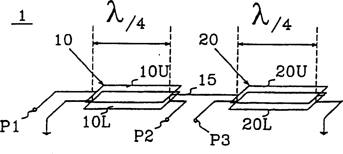
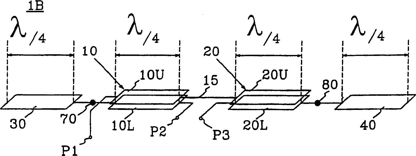
[0016] To provide a better understanding of the specific features of this inventive device, first refer to figure 1 with 2 .

[0017] figure 1 A conventional Marchand balun circuit comprising first and second sub-circuits 10 and 20, respectively, is shown. The first sub-circuit 10 includes an upper conductor 10U, a lower conductor 10L and a dielectric layer disposed between the conductors. The upper conductor 10U and the lower conductor 10L in the first sub-circuit 10 are capacitively and inductively connected together with a given coupling constant. The first sub-circuit 10 corresponds or substantially corresponds to the first λ / 4 waveguide. Likewise, the second sub-circuit 20 includes an upper conductor 20U, a lower conductor 20L and a dielectric layer disposed between the conductors. The upper conductor 20U and the lower conductor 20L are capacitively and inductively connected to one another in the second subcircuit 20 with a given coupling constant. The second sub-ci...


PUM


Abstract

The present invention relates to a balun circuit (1B) comprising a first sub-circuit (10) and a second sub-circuit (20) which each correspond to, or essentially to, a lambda / 4-wave guide. The first sub-circuit (10) includes a first conductor (10U), a second conductor (10L) and a dielectric layer disposed between said first and second conductors, said conductors being connected together capacitively and inductively. The second sub-circuit (20) includes a first conductor (20U), a second conductor (20L) and a dielectric layer disposed between said first and second conductors, said conductors being connected together capacitively and inductively. A first side on the first conductor (10U) in the first sub-circuit (10) is connected to an input port (P1). A second side on the first conductor (10U) in the first sub-circuit (10) is connected to a first side on the first conductor (20U) in the second sub-circuit (20) via a connecting conductor (15). A second side on the second conductor (10L) in the first sub-circuit (10) is connected to a first output port (P2). A first side on the second conductor (20L) in the second sub-circuit (20) is connected to a second output port (P3). A first open terminating lambda / 4-wave guide (30) is connected to a second side on the second conductor (10L) in the first sub-circuit (10), and a second open terminating lambda / 4-wave guide (40) is connected to a second side of the second conductor (20L) in the second sub-circuit (20).

Description

technical field [0001] The invention relates to a balanced-to-unbalanced switching circuit (BALUN) comprising a balanced-to-unbalanced switching circuit each corresponding to a first subcircuit and a second subcircuit of a λ / 4 waveguide, Wherein the first sub-circuit comprises an upper conductor, a lower conductor and a dielectric layer arranged between the upper conductor and the lower conductor, wherein the conductors are capacitively and inductively connected together, wherein the second sub-circuit comprises an upper a conductor, a lower conductor, and a dielectric layer disposed between the upper conductor and the lower conductor, the conductors are capacitively and inductively connected together, wherein the upper conductor located in the first sub-circuit The first side on the upper conductor is connected to an input port, the second side on the upper conductor in the first sub-circuit is connected to the first side of the upper conductor in the second sub-circuit via a...

Claims


Application Information

Patent Timeline
IPC IPC(8): H01P5/10
CPCH01P5/10
Inventor D·维斯特贝里
Owner INFINEON TECH AG
Learn More