Load driver

A carrier-driven, carrier-based technology, applied to valve devices, devices to prevent accidental or unauthorized actions, valve operation/release devices, etc., can solve problems such as accidents in load-driven devices, and ensure safety and operation Efficiency improvement and load reduction effect

Inactive Publication Date: 2004-10-27
WEST ELECTRIC CO LTD
View PDF1 Cites 0 Cited by
  • Summary
  • Abstract
  • Description
  • Claims
  • Application Information

AI Technical Summary

Problems solved by technology

[0007] As mentioned above, using the original load body driving device, in the case of emergency or maintenance, the main shaft is rotated and driven by the manual handle, and the waterway is opened and closed through the gate or valve. If the manual handle is operated due to curiosity or mischief, accidents may occur unknowingly to the load drive device.

Method used


Image

  • Load driver
  • Load driver
  • Load driver

Examples


Embodiment Construction

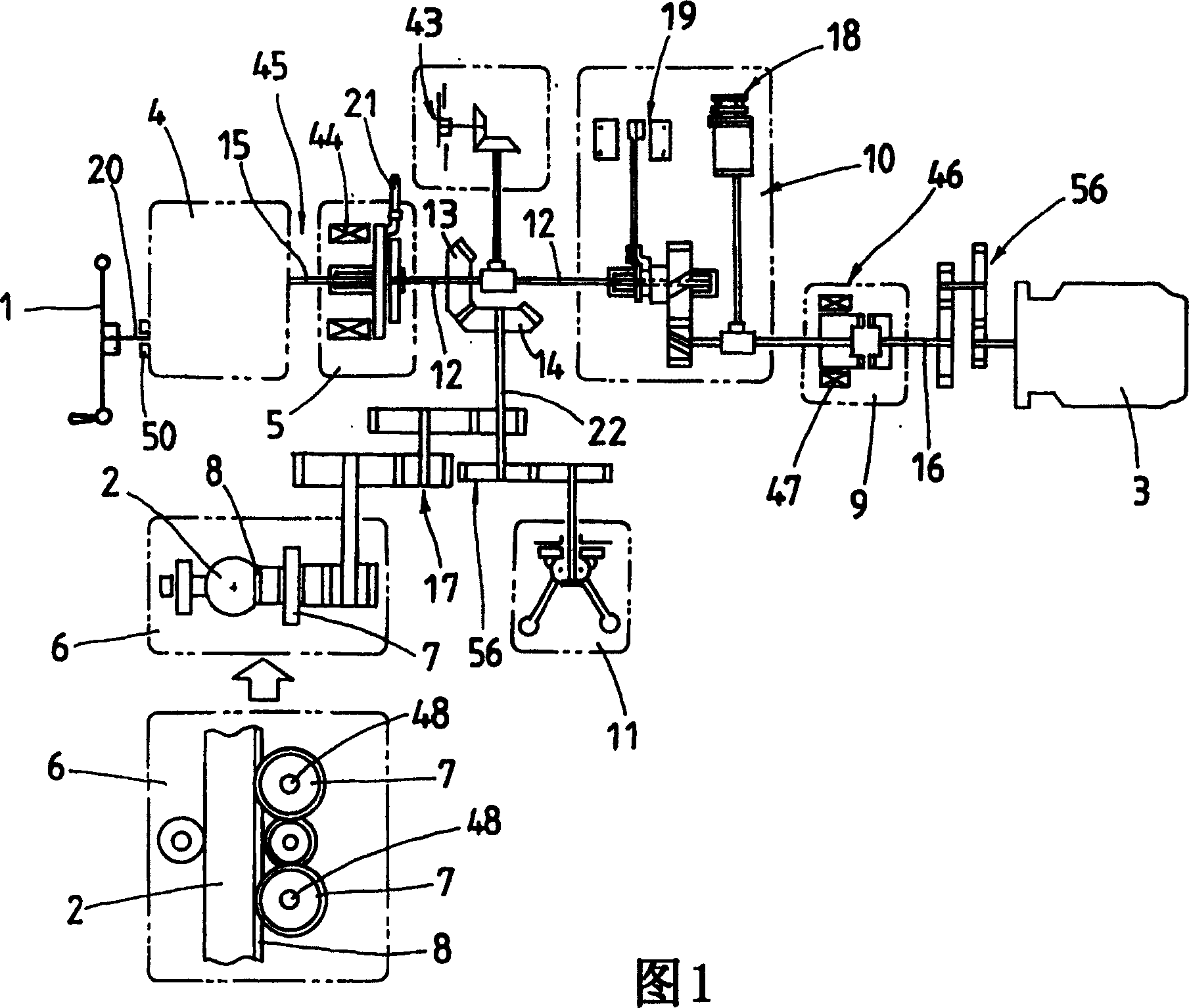
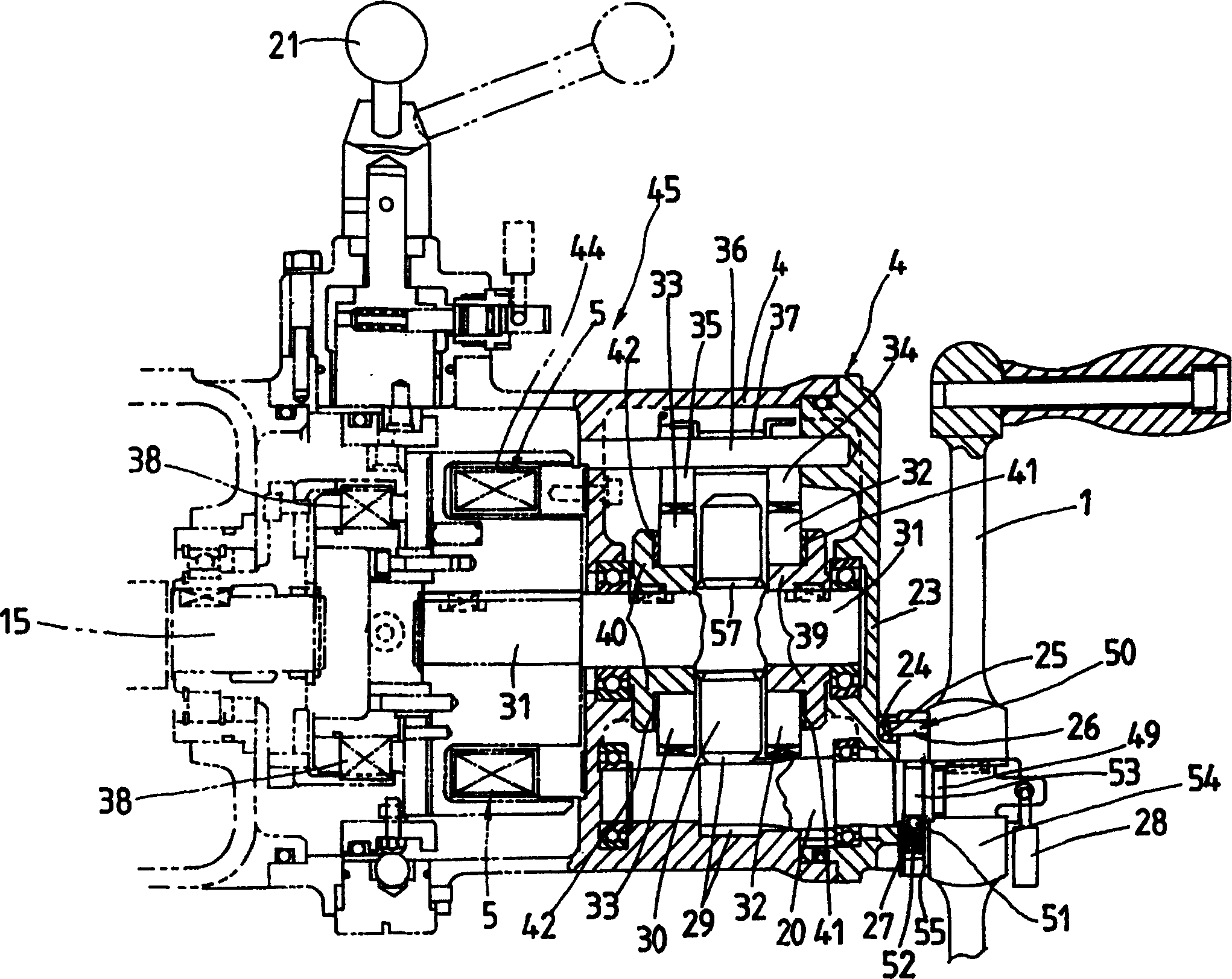
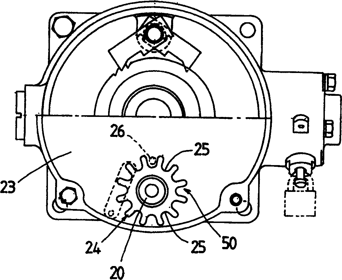
[0025] Embodiments of the load driving device of the present invention will be described below with reference to the accompanying drawings. The load body drive device is provided with: a power transmission device for driving up and down load bodies (not shown) such as weir plates, gates, door bodies, valves, etc. used to control the fluid flow in pipelines such as waterways and tap water; The operation of the handle 1 is interlocked with a manual handle interlock mechanism 50 . The main components of the load drive device are: the main shaft 2 on which the load is mounted; the rack and pinion mechanism 6 for raising and lowering the main shaft 2; the power transmission device 17 having a speed reducer 56 and the like; The 1st clutch 5 that electromagnet 44 and multi-plate disc 38 constitute; The 2nd clutch 9 that is constituted by the electromagnet 47 that is located in the electric drive system 46; Constitute the screw brake 4 of the self-locking mechanism located in the man...


PUM


Abstract

The present load body driving device efficiently operates a load body vertically and provides a clutch lowering by its self-weight of the load body in a part where torque is small. This load body driving device has load bodies provided on the channels such as weir plates, valves and strobes and so on, an output driving shaft for vertically driving a spindle to which the load body is attached through a power transmission device, a manually operated handle driven by and connected with a manually operated driving shaft in a manually operated driving system connected with the output driving shaft through the first clutch, a screw brake constituting a self-lock mechanism assembled into the manually operated driving system, a motor connected with the output driving shaft through the second clutch, and a lock mechanism capable of operating a locking piece provided in the manually operated handle so as to engage it with or disengage it from an engaging part provided in a housing of the female screw brake to rotate or lock the manually operated handle.

Description

technical field [0001] The present invention relates to a load body driving device, which is a power transmission device for moving up and down the main shaft supporting the load body in order to move up and down load bodies such as gates, gate bodies, weir plates, valves, etc. A manual drive system and an electric drive system are installed on it. Background technique [0002] In the past, load bodies such as weir plates, gates, and valves for opening and closing waterways and controlling flow were installed on waterways, waterworks, power plants, and rivers. In order to operate a load installed on a waterway, an operating device for driving a valve, that is, a load drive device can be used. The load body driving device used to operate the valve is developing towards the central information system for control by the controller. At the same time, a controller that can easily control the opening and closing of the valve is provided. For example, it is known in JP-A-11 - Con...

Claims


Application Information

Patent Timeline
Patent Type & Authority Patents(China)
IPC IPC(8): E02B7/20E02B7/36F16K31/44F16K35/02F23D14/72F24C3/12
Inventor 朽原彪
Owner WEST ELECTRIC CO LTD
Why Eureka
Try Eureka