
Centrifugal pressurized separators and methods of controlling same

A separator and pressure sensor technology, applied in separation methods, centrifugal separation water/sewage treatment, chemical instruments and methods, etc., can solve problems such as difficulty in separation, and achieve the effect of reducing the amount of liquid and preventing the phenomenon of vortex transmission.

Inactive Publication Date: 2004-09-15
思想保护有限责任公司
View PDF4 Cites 0 Cited by
  • Summary
  • Abstract
  • Description
  • Claims
  • Application Information

AI Technical Summary

Problems solved by technology

Separation becomes more difficult due to close density

Method used


Image

  • Centrifugal pressurized separators and methods of controlling same
  • Centrifugal pressurized separators and methods of controlling same
  • Centrifugal pressurized separators and methods of controlling same

Examples


Embodiment Construction

[0046] The present invention relates to a system for purifying water contaminated with particulate matter, both organic and non-organic.

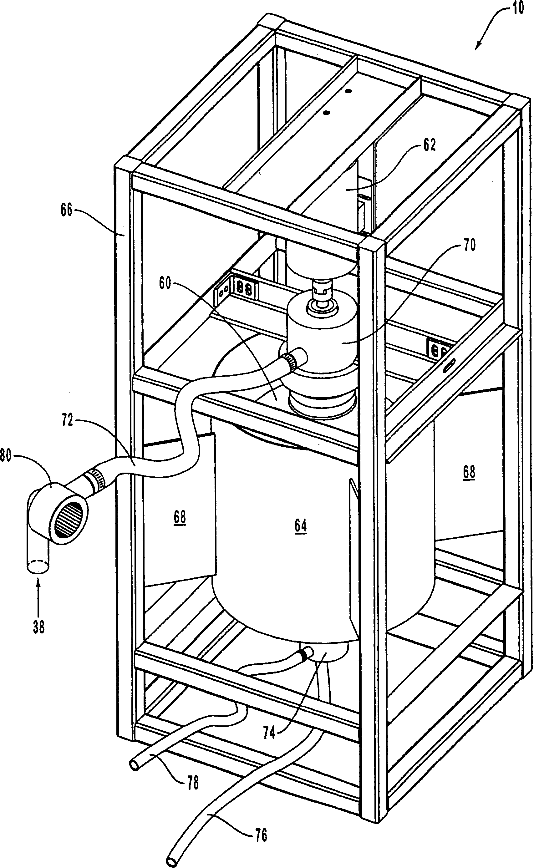
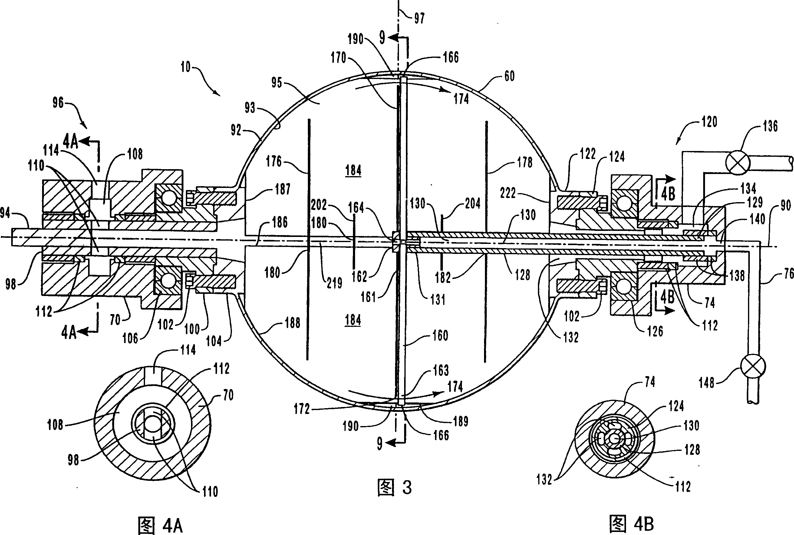
[0047] The invention also relates to a system for separating immiscible liquid (for example separating an oil / water) mixture. Referring now to the drawings, in which like reference numerals indicate like parts, operations or structures. The figures should be regarded as schematic and / or schematic and not necessarily drawn to scale, nor do they limit the spirit and scope of the present invention.

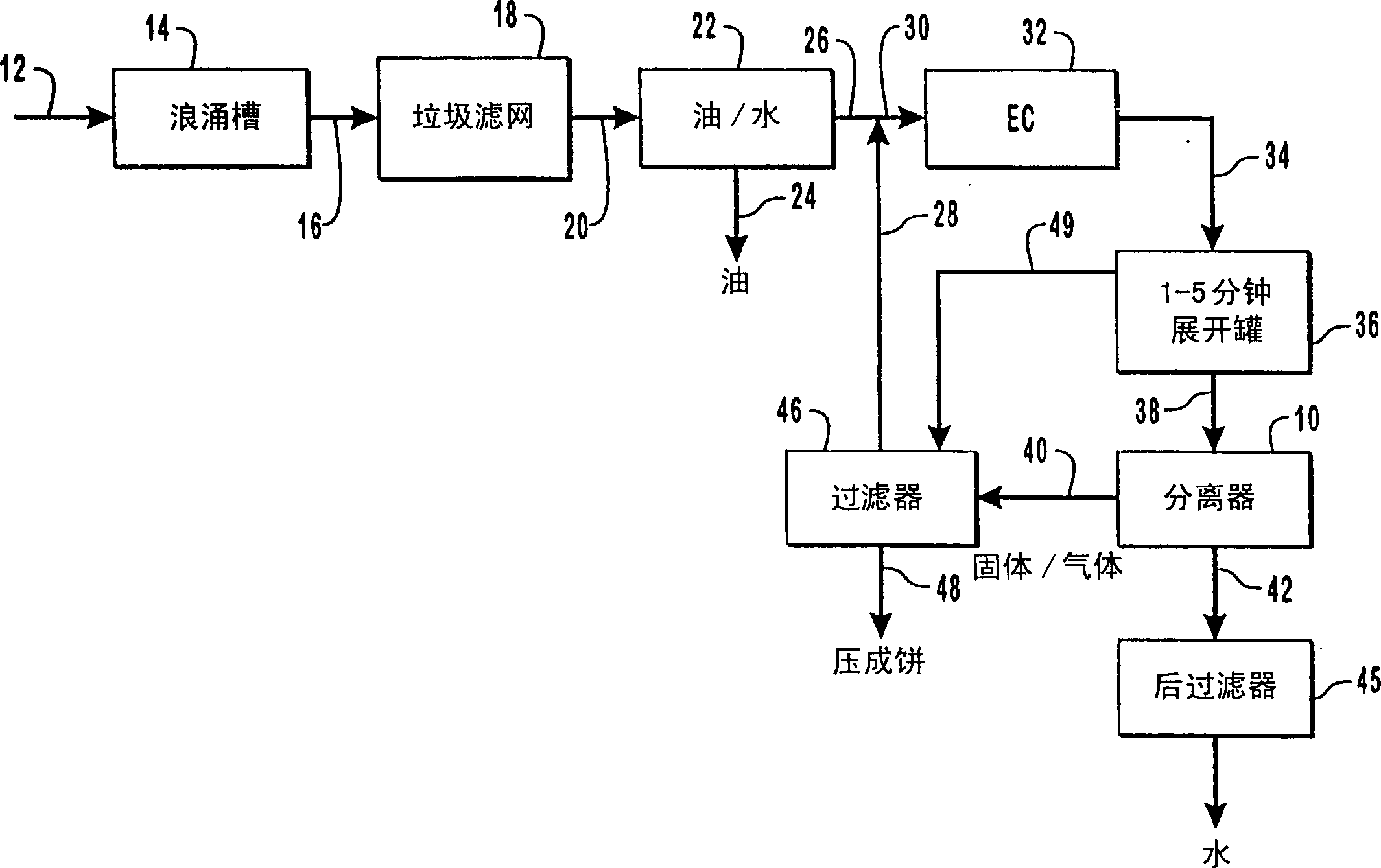
[0048] figure 1 is a general structure diagram of a process using the solid-liquid separator of the present invention; as figure 1 As illustrated in , a solid-liquid separator 10 is connected to a series of other process components. A configuration may include a source stream 12 comprising a stream of material to be processed. Feed stream 12 may include a wide variety of components, such as water including contaminants such as oils, bacterial ...


PUM


Abstract

A solid-liquid / liquid-liquid separator includes a vessel having a peripheral wall bounding a chamber. The chamber communicates with an inlet port and an outlet port. The vessel is rotatable about a rotational axis extending through the vessel. Disposed within the chamber are a number of fins. Each of the fins radially outwardly projects from the rotational axis in substantially parallel alignment with the rotational axis. The fins interact with the peripheral wall to form a plurality of discrete flow channels that longitudinally extend through the vessel. An exit tube is disposed along a portion of the rotational axis of the vessel. The exit tube has a first end disposed within the chamber and an opposing second end in fluid communication with the exterior of vessel. A plurality of extraction tubes radially outwardly projecting from the rotational axis within the chamber. The extraction tubes have a first end in fluid communication with the exit tube and an opposing second end disposed a distance from the peripheral wall. A solid-liquid or liquid-liquid mixture is fed into the rotating pressure vessel and the elements thereof are separate by centrifugal force. Overflow material exits through the outlet port. Underflow material is drawn into the extraction tubes and exits the vessel through the exit tube.

Description

technical field [0001] The present invention relates to a centrifugal separator system for treating water contaminated with organic and inorganic matter. In a first embodiment, the invention relates to a rotary pressure vessel capable of separating solids from liquids at high speed. In another embodiment, the invention relates to a liquid-liquid separator responsive to excessive load disturbances. Background technique [0002] For a long time, water purification has been an activity that people have been constantly trying to obtain drinking water and water for industrial use. With increasing levels of industrialization, water purification has taken on a new and more important place, since industrial use of water often involves the release of contaminated water into the environment. With increasing environmental concerns, the release of water into the environment has been subject to ever higher standards. As a result, greater efforts have been made to find methods of treat...

Claims


Application Information

Patent Timeline
Patent Type & Authority Patents(China)
IPC IPC(8): B04B1/02B04B1/04B04B11/02C02F1/00C02F1/38C02F1/40C02F1/463C02F1/467C02F9/00
CPCB04B11/02C02F9/00C02F1/40B04B1/04C02F1/001C02F1/467B04B1/02C02F1/463C02F1/38
Inventor 凯文·E·卡力尔
Owner 思想保护有限责任公司
Learn More