A hydrogeological drilling water level automatic acquisition device and method
An automatic collection, hydrogeological technology, applied in drilling equipment and methods, earthwork drilling, drilling equipment, etc., can solve problems such as difficulty in real-time monitoring, and achieve the effect of reducing monitoring errors
- Summary
- Abstract
- Description
- Claims
- Application Information
AI Technical Summary
Problems solved by technology
Method used
Image
Examples
Embodiment 1
[0038] see Figure 1-6 , the present invention provides a technical solution:
[0039] In this embodiment, the same part as in Embodiment 1 will not be repeated, the difference is:
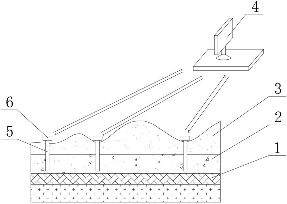
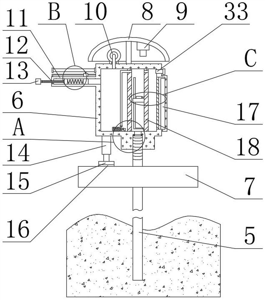
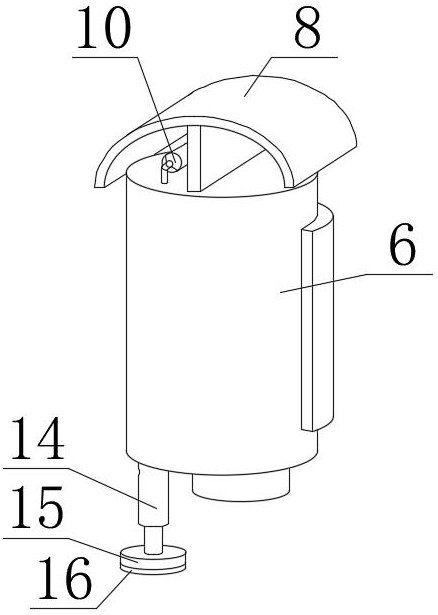
[0040] A hydrogeological drilling water level automatic acquisition device, comprising a water intake pipe 5, a water level acquisition module and a central acquisition host computer 4, the water intake pipe 5 passes through the soil layer 3 and penetrates downward into the aquifer 2 above the aquifer 1, and the water level The acquisition module includes a water level acquisition box 6 and a data transmission module 9. The data transmission module 9 is used for exchanging information between the water level acquisition module and the central acquisition host computer 4. The outside of the top of the water intake pipe 5 is connected to the inside of the water level acquisition box 6. The water intake pipe The quantity of 5 is at least 3, and the height of the bottom end of the water intake pipe 5...
Embodiment 2
[0043] see Figure 1-6 , the present invention provides a technical solution: the water line information module includes a water level tube 18, a submersible pump 30 and a laser receiver 17, the water level tube 18 is made of glass material, and the water level tube 18 is fixedly arranged on the inside of the water level collection box 6, and the water level The inner side of the top of the pipe 18 communicates with the inner side of the water level collection box 6 through the through hole. The top of the water pipe 5 is connected, the submersible pump 30 is fixedly arranged on the bottom inside of the water level collection box 6, the output end of the submersible pump 30 is connected with the top inside of the water level pipe 18, and the input end of the submersible pump 30 is arranged on the water level collection box 6. Under this arrangement, when the water level of the water level pipe 18 is too high and overflows, and then descends, the submersible pump 30 can pump ou...
Embodiment 3
[0047] see Figure 1-6, the present invention provides a technical solution: the air pressure information module includes an air chamber 11 and a sliding rheostat 28, the inner side of the air chamber 11 communicates with the inner side of the water level collection box 6, and the inner side of the air chamber 11 is slidably connected with a slider 25, when the groundwater After the level changes, the water level in the water level pipe 18 and the water intake pipe 5 changes. Correspondingly, the pressure inside the water level collection box 6 will change. When the groundwater level rises, the slider 25 will move to the left. , the slider 25 will move to the right, and the specific position of the slider 25 will be judged by reading the current in the sliding rheostat 28 circuit at this time, and the groundwater depth H at this time will be calculated to realize a wide range of groundwater depth H. Monitoring, the outside of the air cavity 11 is fixedly connected with a secon...
PUM
 Abstract
Description
Claims
Application Information
 - Generate Ideas
- Intellectual Property
- Life Sciences
- Materials
- Tech Scout
- Unparalleled Data Quality
- Higher Quality Content
- 60% Fewer Hallucinations
Browse by: Latest US Patents, China's latest patents, Technical Efficacy Thesaurus, Application Domain, Technology Topic, Popular Technical Reports.
© 2025 PatSnap. All rights reserved.Legal|Privacy policy|Modern Slavery Act Transparency Statement|Sitemap|About US| Contact US: help@patsnap.com


