Liquid dispensing apparatus

A liquid dispensing device and liquid technology, applied in the direction of liquid spraying device, spraying device, printing, etc., can solve the problem of fast printing that is not suitable for large-scale products

Inactive Publication Date: 2004-09-08
乔尔吉·赫格杜斯 +2
View PDF3 Cites 0 Cited by
  • Summary
  • Abstract
  • Description
  • Claims
  • Application Information

AI Technical Summary

Problems solved by technology

[0009] As mentioned above, these known techniques are not suitable for fast printing of large format products

Method used


Image

  • Liquid dispensing apparatus
  • Liquid dispensing apparatus
  • Liquid dispensing apparatus

Examples


Embodiment Construction

[0042] Best Mode for Carrying Out the Invention

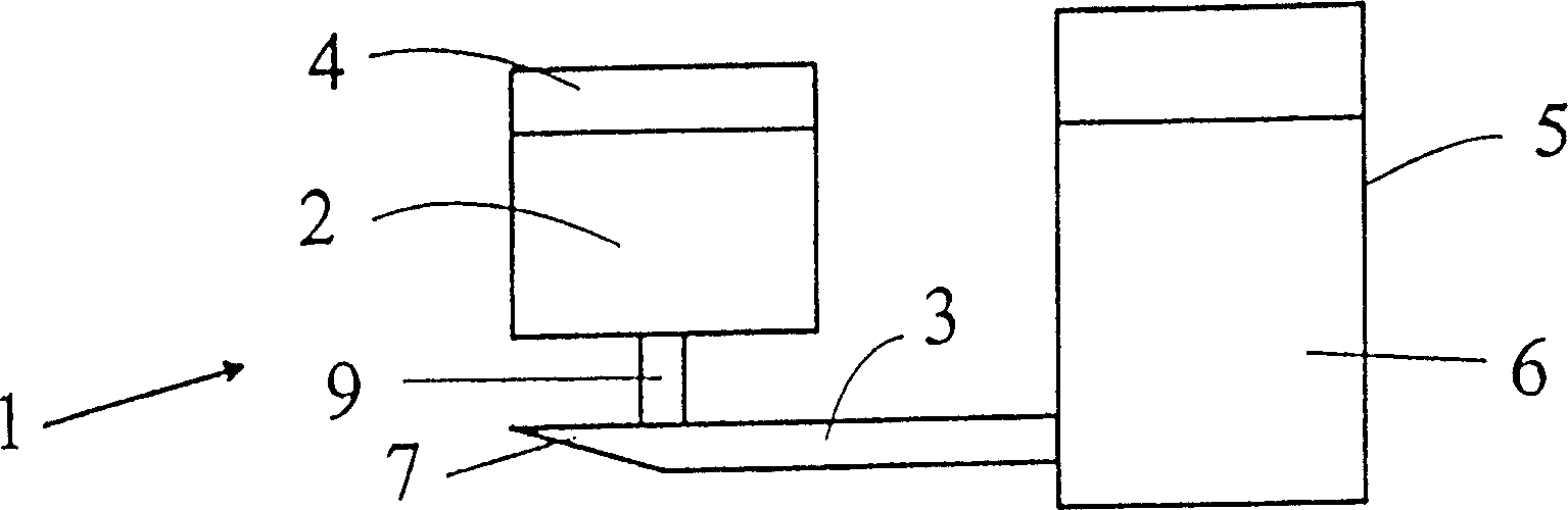
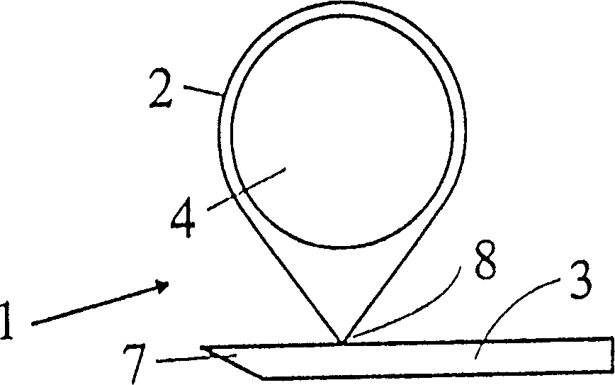
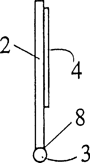
[0043] figure 1 The basic structure of a liquid dispensing device 1 is shown. The device 1 is equipped with a resonator 2 in the form of a metal plate, which is connected to a liquid supply pipe having a nozzle 7 . The liquid supply pipe is a liquid catheter 3 having a free end, the free end ends in a nozzle 7 , and the other end of the liquid catheter 3 is connected to a liquid storage container 5 . The liquid 6 to be dispensed by the nozzle 7 is stored in the liquid storage container 5 .

[0044] Said device 1 is also provided with vibration means, here a transducer 4 . The transducer 4 is capable of causing the resonator 2 to vibrate, and the transducer 4 is fixed with the resonator 2 . The transducer 4 is preferably a piezoelectric transducer, such as a piezoelectric ceramic plate. The resonance mode of the resonator 2 structurally includes a thickness mode, a radial mode, or a bending mode. However, in a preferred em...


PUM


Abstract

There is disclosed a device for dispensing liquids, in particular dyes or inks. The device comprises a liquid tank (5), a dispensing nozzle (7), and a liquid conduit (3) with an end connected to the liquid tank for supplying liquid from the liquid tank to the dispensing nozzle. The device is provided with vibrator means, particularly a piezoelectric transducer (4). The transducer is used for inducing a vibrating action of the dispensing nozzle, and by the vibrating action resulting in an acceleration of the nozzle, to an extent that is sufficient to cause the detachment of the liquid from the nozzle. The invention also relates to a printing head and system utilising the inventive dispensing device.

Description

technical field [0001] The present invention relates to a liquid dispensing device. The device according to the invention comprises a liquid storage container, a dispensing nozzle and a catheter, one end of which is connected to the liquid storage container to supply liquid from the liquid storage container to the dispensing nozzle . The device is especially suitable for the precise dispensing of small quantities of liquids, especially paints, medicaments or similar liquids which must be dispensed in very precise and controllable portions. The invention also relates to a print head and a printing system using the dispensing device according to the invention. Background technique [0002] Various liquid dispensing devices having a dispensing nozzle are known in the art. US Patent No. 3,653,598 to Waldrum discloses a vibratory spraying device for use in agricultural spraying systems. This known device comprises a spray tube with an associated vibration transmission device....

Claims


Application Information

Patent Timeline
Patent Type & Authority Patents(China)
IPC IPC(8): B41JB41J2/02B41J2/025B41J2/135
CPCB41J2/025B05B17/0607B41J2/04B05B17/0623
Inventor 乔尔吉·赫格杜斯艾伯特·科克西斯古兹塔夫·弗罗里安
Owner 乔尔吉·赫格杜斯
Why Eureka
Try Eureka