Injector unit for the injection of fuel, and method for the operation of an injector unit of this type

A technology of injectors and fuels, applied in the direction of fuel injection devices, charging systems, engine components, etc., which can solve problems such as premature replacement, increased fuel consumption, and wear of armature stoppers

Pending Publication Date: 2021-09-28
LIEBHERR COMPONENTS DEGGENDORF GMBH
View PDF6 Cites 0 Cited by
  • Summary
  • Abstract
  • Description
  • Claims
  • Application Information

AI Technical Summary

Problems solved by technology

Therefore, this time variation means that the injection quantity is controlled relatively conservatively, resulting in increased fuel consumption
[0010] In addition, armature flutter causes wear of the armature and the stop that strikes on it, which can lead to premature replacement of one of the two components

Method used


Image

  • Injector unit for the injection of fuel, and method for the operation of an injector unit of this type
  • Injector unit for the injection of fuel, and method for the operation of an injector unit of this type

Examples


Embodiment Construction

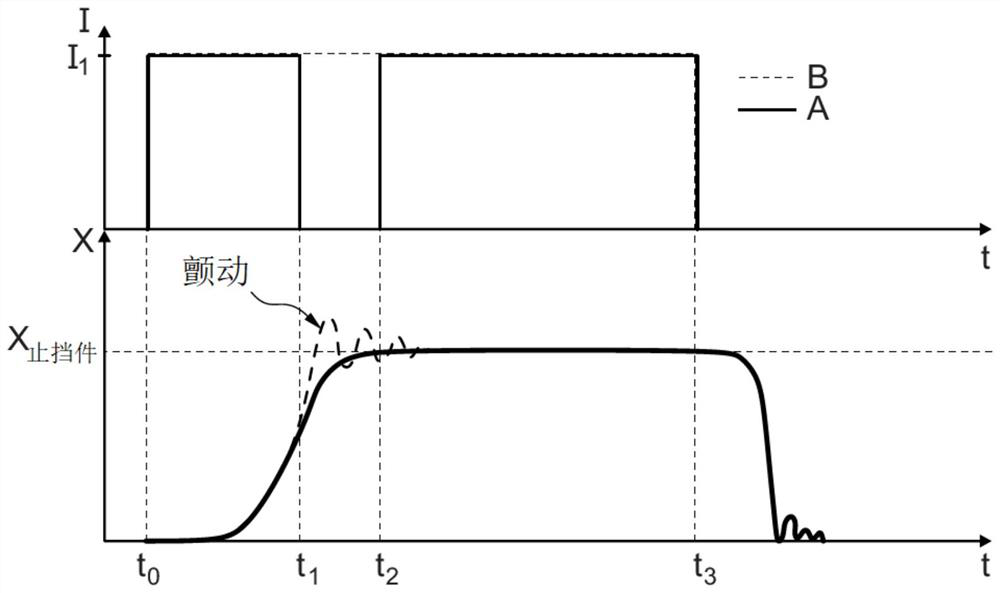
[0041] figure 1 Shows two diagrams superimposed over time t, wherein the upper one of the two diagrams shows the actuation signal I or the electromagnetic signal guided to the electromagnetic signal according to the invention (solid line A) and according to the prior art (dotted line B). The direction of the current in the iron. The graph located below shows the displacement (x) of the armature element as a function of various actuation signals, where the dotted line represents the control behavior according to the prior art and the solid line represents the control according to the invention.

[0042] From the graph, it can be seen that at time t 0 The armature element is placed on the seat plate such that the through hole is sealed.

[0043] now at time t 0 Set the current signal I used to control the electromagnet to the value I 1 , which is non-zero and therefore causes the armature element to move from the seat plate towards the lift-limiting stop, the armature elemen...


PUM


Abstract

In accordance with the invention, an injector unit for the injection of fuel comprises a seat plate with a through opening which extends through the seat plate; an armature element which can be placed onto the seat plate, in order to close the through opening; a spring element which pushes the armature element in the direction of the seat plate, in order to close the through opening; an electromagnet which is designed to load the armature element with a force, in order to lift the armature element from the seat plate; and a stop for limiting a stroke of the armature element in a state in which it is lifted from the seat plate. The injector unit is characterized by a control unit which is designed to reduce an actuating signal of the electromagnet for lifting the armature element from the seat plate before the armature element makes contact with the stop for the first time after being lifted from the seat plate.

Description

technical field [0001] The invention relates to an injector unit for injecting fuel and a method for operating the injector unit. Background technique [0002] In an internal combustion engine such as a diesel engine or a gasoline engine, a certain amount of fuel is usually injected into the combustion chamber by means of an injector for a certain period of time. Due to the extremely short injection durations in the microsecond range, it is required that the vent holes of the injectors be opened and closed very frequently. [0003] Since those skilled in the art are familiar with the basic functional principles of injectors, only a few aspects that facilitate an understanding of the invention are briefly discussed below. [0004] Injectors typically have a nozzle needle (also known as an injector needle) that releases high-pressure fuel when at least one outlet of the injector is open. The nozzle needle acts like a plug when interacting with the at least one outlet, releas...

Claims


Application Information

Patent Timeline
Patent Type & Authority Applications(China)
IPC IPC(8): F02M63/00
CPCF02M63/0017F02D2041/2037F02M63/0075F02D41/20F02D2041/2024F02M47/027F02D2041/2058
Inventor R·皮尔克R-S·斯廷赫M·赛德尔
Owner LIEBHERR COMPONENTS DEGGENDORF GMBH
Why Eureka
Try Eureka