Positioning punch pin

A technology for positioning punches and punches, which is applied in metal processing and other directions, and can solve problems such as difficult operations

Inactive Publication Date: 2004-07-28
CARL JIMUKI
View PDF0 Cites 0 Cited by
  • Summary
  • Abstract
  • Description
  • Claims
  • Application Information

AI Technical Summary

Problems solved by technology

[0005] However, if there is no table on which to place the locator, the locator must be held in one hand while operating, which is difficult to operate, especially for operators with small hands

Method used


Image

  • Positioning punch pin
  • Positioning punch pin
  • Positioning punch pin

Examples


Embodiment Construction

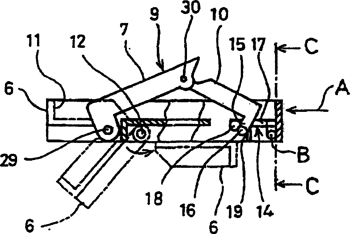
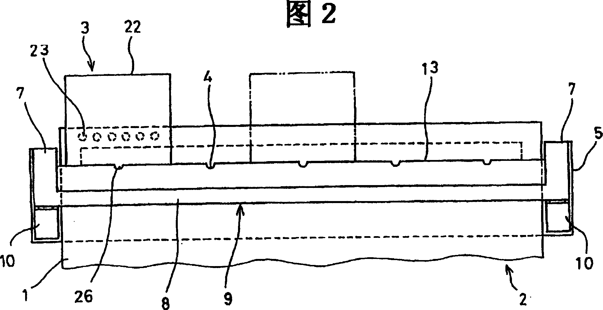
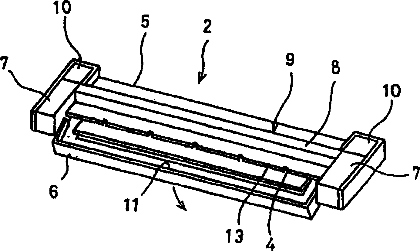
[0024] Refer below Figure 1-7 An embodiment of the present invention is described. First, the outline of the positioning punch of this embodiment will be described. As shown in FIG. 2, the positioning punch of the present invention includes a positioner 2 holding paper 1 and a punch 3 forming a designated binding hole, wherein the punch 3 is placed on a plurality of positions selectively provided on the positioner 2. On the punch positioning part 4, a plurality of designated binding holes are set at selected positions on the paper 1, so that the desired binding holes are finally formed on the paper 1.

[0025] Next, the components of the positioner 2 according to the embodiment of the present invention will be described in detail. like Figure 1-3 As shown in , the positioner 2 includes a bottom plate 5, a scale 6, a paper holder part 9 and a link part 10, the scale 6 positions the paper 1 by pressing against the paper, and the paper holder part 9 is formed on the paper ho...


PUM


Abstract

a positioning punch pin is provided to easily cause a gauge to hold a paper sheet even in a state to be held by a hand holding the positioner. A link member on which protrusion part is formed is coupled to a paper holding means and the protrusion part is engaged in the given position formed a board. Through so constitution, a paper holding part is maintained opened in a way that the protrusion part of the link member is locked at a lock part formed at an engaging part and by pressing the paper holding part, the protrusion part is released from a lock by the locking part and the paper holding part holds a paper sheet, whereby even with the paper sheet held by a hand, the paper sheet is easily held by the positioner.

Description

technical field [0001] The present invention relates to a positioning punch, in particular, the positioning punch includes a positioner for positioning and holding the paper in position and a punch for punching designated binding holes in the paper. Background technique [0002] When binding documents on the file booklet, it is necessary to punch out the corresponding binding holes of the file booklet. For example, when punching 30 binding holes on the paper of JIS specification (Japanese Industrial Standard) A4, usually use one with a row of 30 holes. Punch head of a punch part. However, in the case where multiple sheets of paper must be punched, there is a problem that a large force must be used to push down the handle of the punch. In addition, since 30 punch parts are set in one row, the The punch body itself is large. [0003] Thus, as shown in FIG. 8, the applicant has invented a positioning punch, which includes a positioning device 102 for positioning the paper 101...

Claims


Application Information

Patent Timeline
IPC IPC(8): B26F1/32B26D7/01B26D7/02B26F1/36
CPCB26D7/025B26D7/015B26F1/36
Inventor 森诚中村知义铃木秀行吴小东
Owner CARL JIMUKI
Why Eureka
Try Eureka