
Air-conditioner (JP)

An air conditioner and air conditioner technology, which is applied in air conditioning systems, high-efficiency regulation technology, space heating and ventilation, etc., can solve the problems of cold wind sensation and the temperature of heat exchangers slowly decreasing, and achieve the effect of preventing cold wind sensation

Inactive Publication Date: 2004-07-07
SANYO ELECTRIC CO LTD
View PDF0 Cites 0 Cited by
  • Summary
  • Abstract
  • Description
  • Claims
  • Application Information

AI Technical Summary

Problems solved by technology

[0007] However, when the compressor is turned off and the cross-flow fan is running, the temperature of the heat exchanger will gradually drop, which will cause a cold feeling due to the wind blown from the indoor unit.

Method used


Image

  • Air-conditioner (JP)
  • Air-conditioner (JP)
  • Air-conditioner (JP)

Examples


Embodiment Construction

[0024] Embodiments of the present invention will be described below with reference to the drawings.

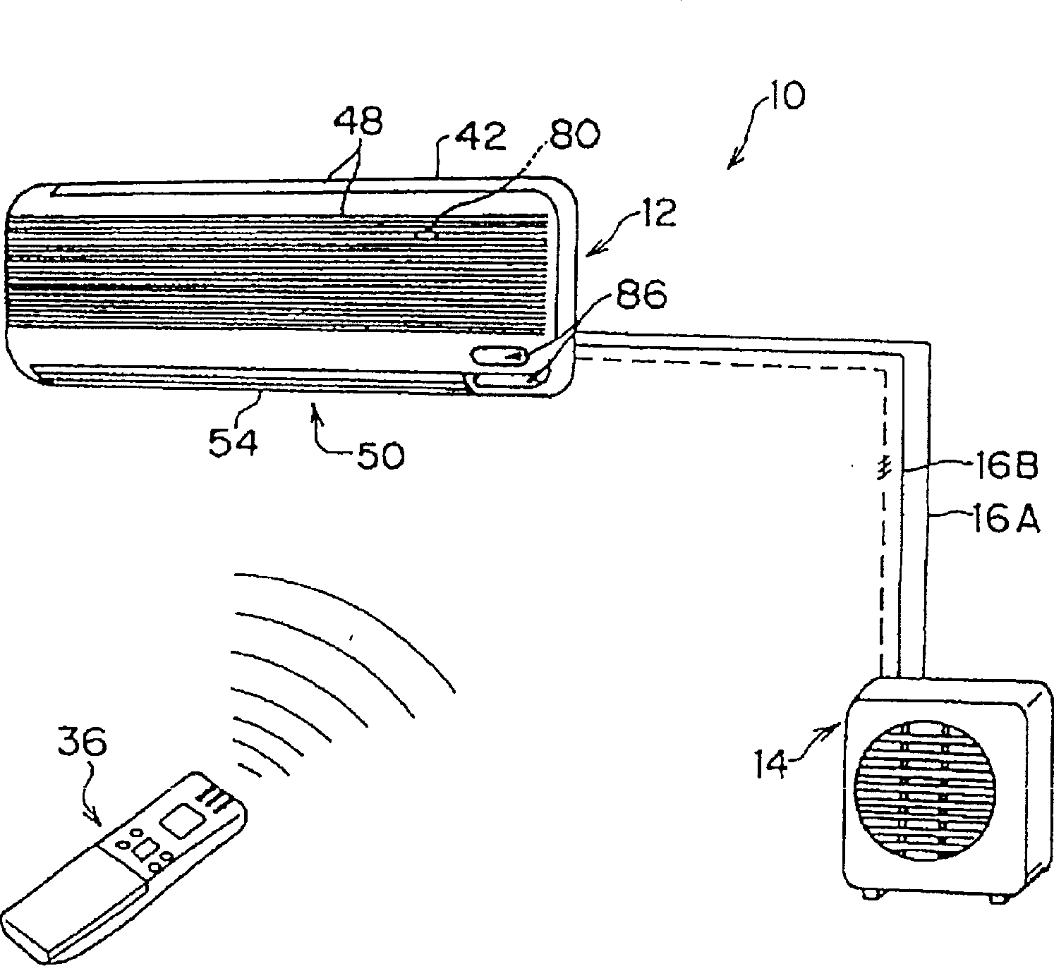
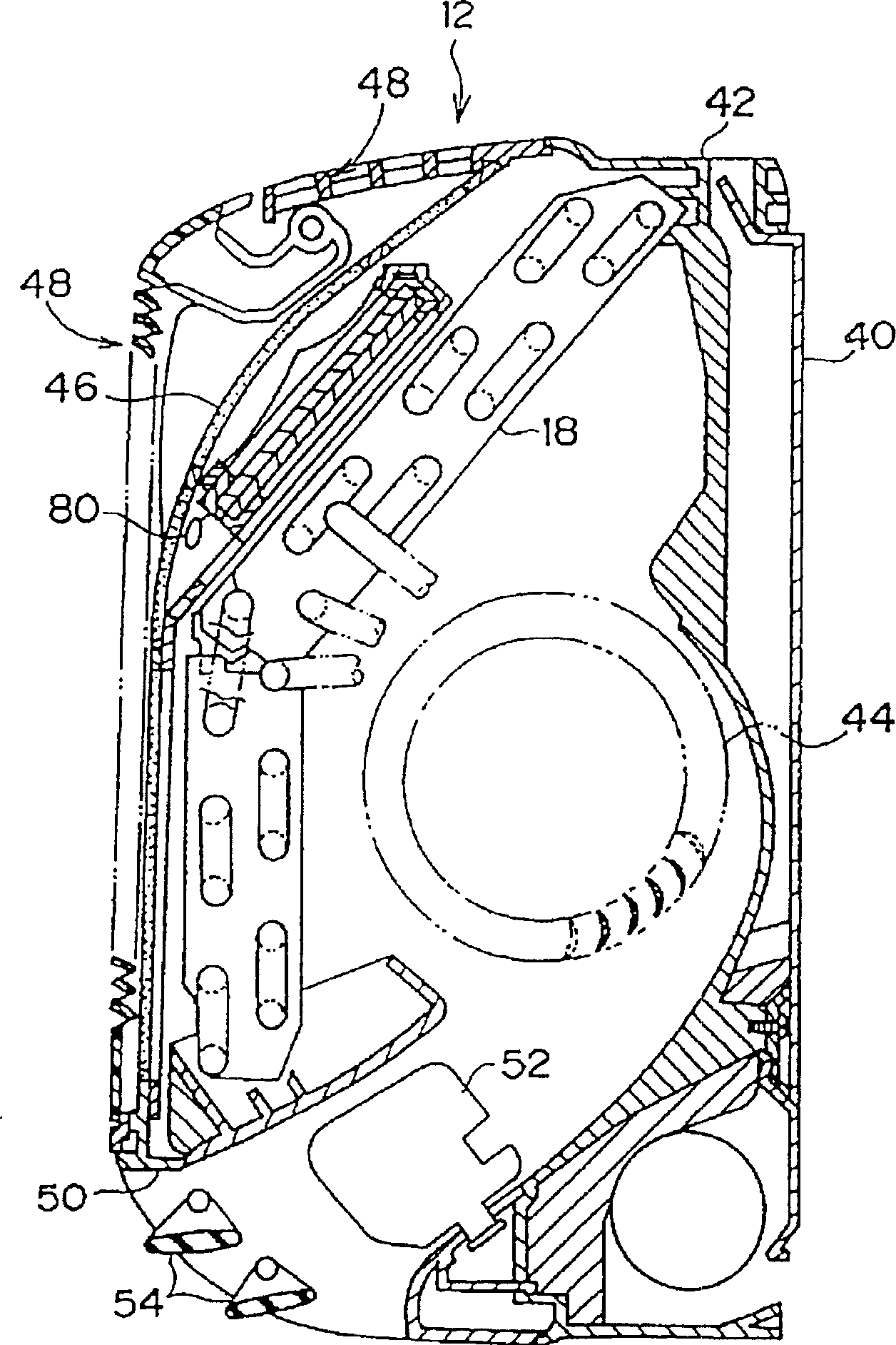
[0025] Such as figure 1 As shown, the air conditioner applicable to this embodiment is divided into an indoor unit 12 installed in an air-conditioned room and an outdoor unit 14 installed outdoors. Under operating conditions such as a fixed temperature, the indoor unit 12 controls the outdoor unit 14 to perform air-conditioning operations.

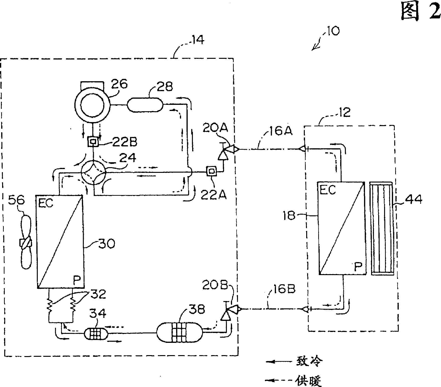
[0026] FIG. 2 schematically shows a refrigeration cycle constituted between the indoor unit 12 and the outdoor unit 14 of the air conditioner 10. As shown in FIG. Between the indoor unit 12 and the outdoor unit 14, a refrigerant line 16A with a large diameter for circulating the refrigerant and a pair of refrigerant lines 16B with a small diameter are provided. It is connected to the heat exchanger 18 in the indoor unit 12.

[0027] The other end of the refrigerant line 16A is connected to the valve 20A of the outdoor unit 14 . Valve 2...


PUM


Abstract

A fan motor is run at minimum capability at predetermined time intervals for a certain period of time when a heating mode is set but a blowing is stopped. Thus, with air around a temperature sensor disposed between inlet openings and a heat exchanger being not affected by the heat of the heat exchanger, measurement of a room temperature is carried out by the temperature sensor.

Description

technical field [0001] The invention relates to an air conditioner, in particular to an air conditioner with a temperature sensor for detecting indoor temperature between a heat exchanger of an indoor unit and a suction port. Background technique [0002] Air conditioners used to adjust indoor air include so-called fixed-speed types that rotate and drive the compressor at a certain number of revolutions and circulate the refrigerant at the same time. There are also indoor units installed indoors and outdoor units installed outdoors in the air conditioner. The so-called split type of unit. [0003] The split-type air conditioner is equipped with a sensor near the suction port of the indoor unit to detect the temperature of the air sucked into the room from the suction port as the indoor temperature. [0004] However, in the constant speed air conditioner, the compressor is turned on / off based on the temperature difference between the temperature detected by the temperature s...

Claims


Application Information

Patent Timeline
Patent Type & Authority Patents(China)
IPC IPC(8): F24F11/02F24F11/00
CPCF24F2221/54Y10S236/09F24F11/0079Y02B30/746F24F11/0012F24F11/30F24F2110/10F24F11/77Y02B30/70F24F11/81F24F11/84F24F11/76F24F11/88F24F11/79F24F11/63F24F11/86F24F11/89F24F11/74
Inventor 香月光
Owner SANYO ELECTRIC CO LTD
Learn More