Fuse box device

A technology of fuse boxes and fixing devices, which is applied in the direction of emergency protection devices, fuse manufacturing, electrical components, etc., can solve the problems of miniaturization difficulties, achieve the effects of low manufacturing cost, avoid false assembly, and reduce the number of components

Inactive Publication Date: 2004-05-12
SUMITOMO WIRING SYST LTD
View PDF0 Cites 2 Cited by
  • Summary
  • Abstract
  • Description
  • Claims
  • Application Information

AI Technical Summary

Problems solved by technology

This in turn will make miniaturization more difficult

Method used


Image

  • Fuse box device
  • Fuse box device
  • Fuse box device

Examples


Embodiment Construction

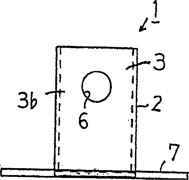
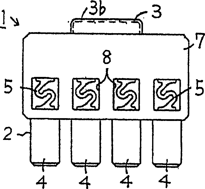
[0026] constitute Figure 2(a) to Figure 2(d) The fuse unit 1 of the shown fuse box device is formed by a conductive sheet, for example a metal sheet. Examples of metals forming the conductive sheet include silver, copper, zinc, tin, lead, and alloys made of one or more of these metals. An input terminal 3 for the battery, an output terminal 4 (male terminal) and a fusible piece portion 5 are integrally formed by the conductive piece. The input terminal 3 is intended to be connected to a power supply terminal of a vehicle battery and comprises a first strip 3a (in normal use arranged vertically) and a second strip 3b (in normal use arranged horizontally). The former is larger than the latter. One end of the second strip 3b (horizontal strip) is connected to the upper end of the first strip 3a (vertical strip). The second strip 3b forms an inverted U-shape when viewed along its cross-sectional view. A substantially circular screw hole 6 for bolt connection is provided at a ...


PUM


Abstract

The fuse box device comprises a fuse box (21) and a fuse unit (1) contained therein. The fuse unit (1) includes an input terminal (3) directly connectable to a battery, several output terminals (4) connectable to a wire harness, and several fuse element portions (5). One end of the fuse element portions (5) is integrally formed with the input terminal (3), whilst the other end of the fuse element portions (5) is integrally formed with the output terminals (4). The fuse unit (1) is contained in the fuse box (21), such that only the input terminal (3) projects out of the fuse box (21). In such a construction, the fuse box device requires a reduced number of spare parts, so that production costs can be lowered. Moreover, the fuse box device is better adapted to a miniaturization and less susceptible to assembling errors.

Description

technical field [0001] The present invention generally relates to a fuse box device, which includes a fuse unit and a fuse box encapsulating the fuse unit. Such a fuse box device can usually be fitted directly to a battery contained in the vehicle. Background technique [0002] An example of a known fuse box device is shown in FIG. 1 . In this figure, the fuse box device 61 includes a fuse box 62 in which many flat fuses 63 are arranged. Such flat fuses 63 consist of a conductive sheet metal, and they each include a fusible piece portion 64 between two ears, each ear having a corresponding ear hole 65 for bolting. The fuse box 62 is made by molding resin. It has a cavity 66 which can contain a number of flat fuses 63 . The base of the cavity 66 is provided with one or more flat input nuts 67 and flat output nuts 68 . Both flat nuts 67 and 68 are insert molded. The flat input nut 67 is secured to a terminal which is directly connected to a battery (not shown in the figu...

Claims


Application Information

Patent Timeline
IPC IPC(8): H01H69/02H01H85/044H01H85/20
CPCH01H2085/0034H01H69/02H01H2085/0555H01H85/2045H01H85/044
Inventor 角田达哉
Owner SUMITOMO WIRING SYST LTD
Why Eureka
Try Eureka