Rotating electric machine system

A technology for rotating motors and rotating shafts, which is applied to motors, rotating bearings, mechanical equipment, etc., and can solve problems such as inaccurate test results or inaccurate test results.

Pending Publication Date: 2022-08-09
HONDA MOTOR CO LTD
View PDF2 Cites 0 Cited by
  • Summary
  • Abstract
  • Description
  • Claims
  • Application Information

AI Technical Summary

Problems solved by technology

If the electromagnetic coil and terminals are heated, it will affect the rotation parameter detector and temperature measuring instrument, and as a result, there is a possibility that the detection result or measurement result will be inaccurate.

Method used


Image

  • Rotating electric machine system
  • Rotating electric machine system
  • Rotating electric machine system

Examples


Embodiment Construction

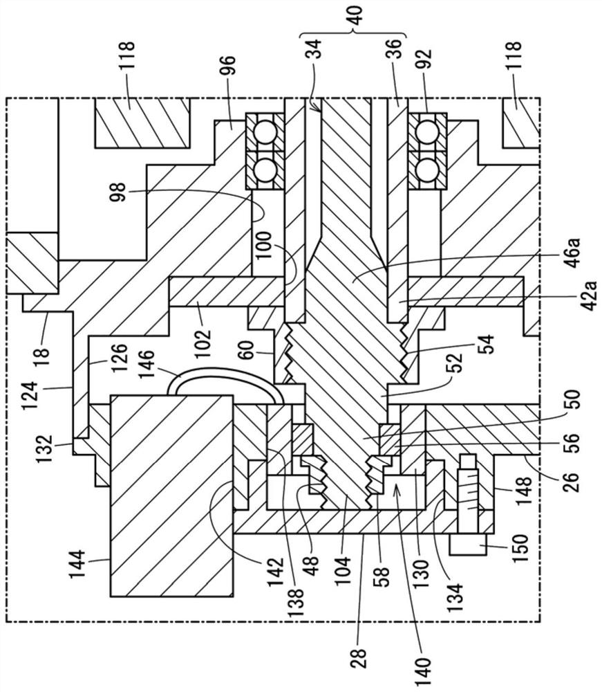
[0026] Hereinafter, the rotating electrical machine system according to the present invention will be described in detail with reference to the accompanying drawings by citing preferred embodiments. In addition, "left", "right", "bottom" and "top" in the following description respectively refer to Figure 2 to Figure 9 Left, Right, Below, and Above in . However, these directions are convenient directions to simplify the description and make it easier to understand. That is, the directions shown in the specification are not necessarily the directions when the rotary electric machine system is actually used.

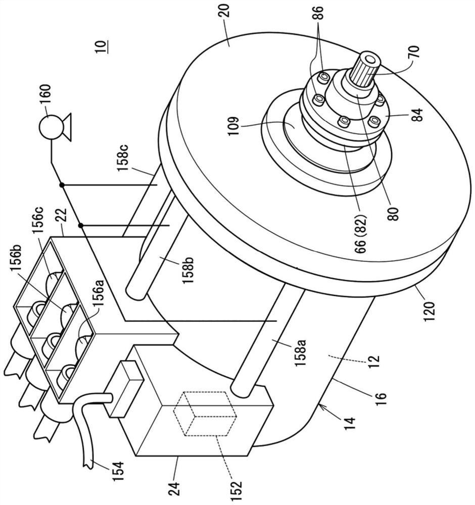
[0027] figure 1 It is a schematic overall perspective view of the rotating electrical machine system 10 according to the present embodiment. figure 2 It is a schematic side cross-sectional view of the rotating electrical machine system 10 . The rotating electrical machine system 10 includes a rotating electrical machine 12 (eg, a generator) and a housing 14 that accom...


PUM


Abstract

The invention provides a rotating electrical machine system. A rotating electrical machine system (10) is provided with a rotating electrical machine (12) having a rotating shaft (40), and a housing (14) that houses the rotating electrical machine. A first bearing (92) and a second bearing (94) are provided between the housing (14) and the rotating shaft (40). Gas supplied from a gas supply source outside the housing flows upstream from a terminal housing (22) that houses the electrical terminal sections (156a-156c) and downstream from the housing (14). The first bearing and the second bearing are disposed in the flow path in the housing. Therefore, the worry that the electric terminal part and the like are polluted by the lubricating oil can be eliminated.

Description

technical field [0001] The present invention relates to a rotary electric machine system having a rotary electric machine and a housing in which the rotary electric machine is accommodated. Background technique [0002] A rotating electrical machine has a rotor including a rotating shaft holding permanent magnets, and a stator including electromagnetic coils. As disclosed in Japanese Patent Laid-Open Publication No. 2016-174443 figure 1 As shown, the rotating shaft is rotatably supported by a housing in which the stator is accommodated via a bearing. In addition, the rotating electrical machine is a generator when the current generated in the electromagnetic coil accompanying the rotation of the rotor is output. On the other hand, when power is obtained from a rotating shaft that rotates when the electromagnetic coil is energized, the rotating electrical machine is an electric motor. [0003] The housing is provided with a connector for electrically connecting an external...

Claims


Application Information

Patent Timeline
Patent Type & Authority Applications(China)
IPC IPC(8): H02K9/10H02K9/14H02K5/20H02K11/25
CPCH02K9/10H02K9/14H02K5/20H02K11/25H02K7/083H02K5/1732H02K11/21H02K7/003F16C2380/26F16C19/54H02K5/207H02K5/225F16C17/26
Inventor 矢崎学丁子达也
Owner HONDA MOTOR CO LTD
Why Eureka
Try Eureka