
Low-pressure-difference steady-state vacuum chuck based on stepped conical flow channel

A vacuum suction cup and conical flow technology, applied in the field of tooling and fixtures, can solve the problems of uneven placement of chips, inconvenient separation of the top cover and base, and inconvenient rapid positioning of chips, so as to achieve high processing efficiency, improve heat transfer efficiency, The effect of simple structure

Active Publication Date: 2022-08-09
中科领航医疗科技有限公司
View PDF12 Cites 0 Cited by
  • Summary
  • Abstract
  • Description
  • Claims
  • Application Information

AI Technical Summary

Problems solved by technology

[0003] At present, for existing vacuum chucks, such as the Chinese patent with the notification number CN209273275U, its surface is smooth and lacks a certain positioning device, which is not convenient for fast positioning of the chip, and the efficiency is low, so that the position of the chip is not uniform, and the stability of the adsorption is poor. , resulting in low chip processing accuracy, such as the Chinese patent with the notification number CN211332308U, the top cover and base of the vacuum suction cup body are inconvenient to separate, and it is difficult to disassemble and replace. It is easy to slip or even collide in the middle, which has certain disadvantages

Method used


Image

  • Low-pressure-difference steady-state vacuum chuck based on stepped conical flow channel
  • Low-pressure-difference steady-state vacuum chuck based on stepped conical flow channel
  • Low-pressure-difference steady-state vacuum chuck based on stepped conical flow channel

Examples


Embodiment Construction

[0034] The present invention will be further described below in conjunction with the embodiments.

[0035] The following examples are used to illustrate the present invention, but cannot be used to limit the protection scope of the present invention. Conditions in the examples can be further adjusted according to specific conditions, and simple improvements to the method of the present invention under the premise of the concept of the present invention all belong to the scope of protection of the present invention.

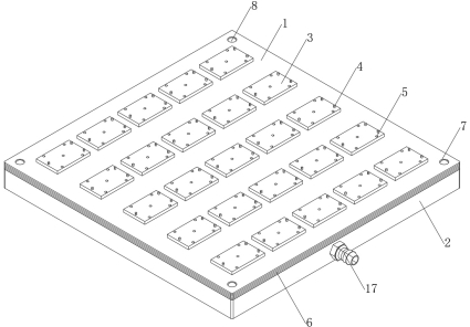
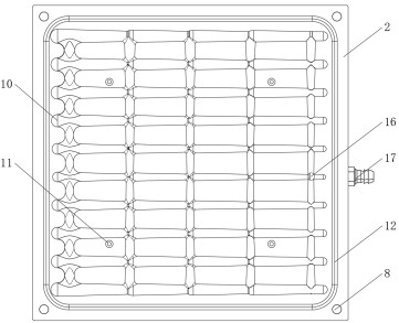
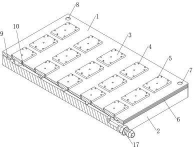
[0036] see Figure 1-10 , the present invention provides a low-pressure differential steady-state vacuum suction cup based on a stepped conical flow channel, comprising a top cover 1 and a base 2, the top of the top cover 1 is fixed with a plurality of bosses 3, and the top of each boss 3 is connected to The bottoms of the plurality of limit posts 4 are fixedly connected, and each boss 3 is also provided with a plurality of suction holes 5, and each suction hole ...


PUM


Abstract

The invention discloses a low-pressure-difference steady-state vacuum chuck based on a stepped conical runner, and belongs to the technical field of tool clamps, the low-pressure-difference steady-state vacuum chuck comprises a top cover and a base, the top of the top cover is fixedly connected with a plurality of bosses, the top of each boss is fixedly connected with the bottoms of a plurality of limiting columns, each boss is further provided with a plurality of air suction holes, and the air suction holes are communicated with the bottom of the top cover. Each air suction hole penetrates through the boss and the top cover, an anti-skid layer is arranged on the side wall of the top cover, and a plurality of positioning holes are formed in the position, close to the anti-skid layer, of the top of the top cover; the top cover and the base are kept relatively stable through cooperation of the positioning holes formed in the top cover and the positioning pins fixedly connected to the base, the top cover and the base are further kept stable through cooperation of the pressing grooves formed in the bottom of the top cover and the sealing strips and the annular grooves, relative movement of the top cover and the base in the chip machining process is avoided, and the chip machining quality is improved. The bottom of the air suction hole is always communicated with the diversion trench, so that the vacuum chuck can operate stably.

Description

technical field [0001] The invention belongs to the technical field of tooling and fixtures, and in particular relates to a low-pressure differential steady-state vacuum suction cup based on a stepped conical flow channel. Background technique [0002] The vacuum chuck is mainly used for positioning and clamping the workpiece in machining. During the machining operation, the positioning device is the key to ensure its machining accuracy. When processing magnetic materials such as iron, the existing electromagnetic chuck can be used for positioning and processing. However, for non-magnetic chips such as rubber, wood, plastic, etc., a vacuum chuck is required. Of course, the vacuum chuck can also process the magnetic chip. [0003] At present, for the existing vacuum suction cup, such as the Chinese patent with the bulletin number CN209273275U, the surface is flat and lacks a certain positioning device, which is inconvenient for the rapid positioning of the chip, and the effic...

Claims


Application Information

Patent Timeline
Patent Type & Authority Applications(China)
IPC IPC(8): H01L21/683
CPCH01L21/6838
Inventor 唐果胡赞周典航朱银锋余钰洋宋钢
Owner 中科领航医疗科技有限公司
Learn More