
Micro strain sensor

A sensor and micro-strain technology, applied in the sensor field, can solve the problems of reducing the strain core area, overloading the sensor, easily exceeding the measurement range of the sensor, etc., and achieving the effects of simple mechanical structure, fast response, and simple device structure

Pending Publication Date: 2022-08-09
安徽智敏电气技术有限公司
View PDF0 Cites 0 Cited by
  • Summary
  • Abstract
  • Description
  • Claims
  • Application Information

AI Technical Summary

Problems solved by technology

[0003] Due to the high sensitivity of the micro-strain sensor, reducing the stiffness of the strain core area, or designing the structure to amplify the force to be measured, it is easy to exceed the measurement range of the sensor, resulting in overload damage to the sensor

Method used


Image

  • Micro strain sensor
  • Micro strain sensor
  • Micro strain sensor

Examples


Embodiment

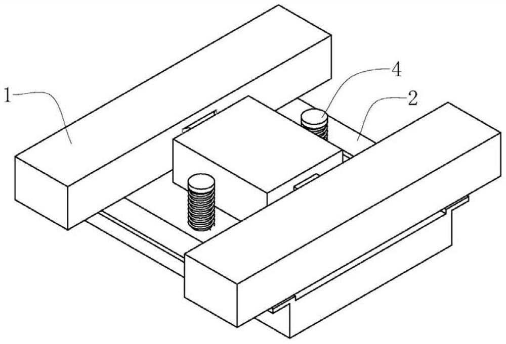
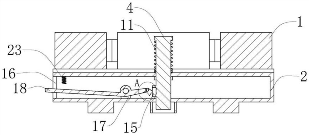
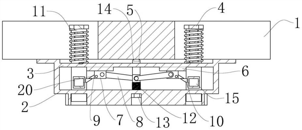
[0021] Example: as Figure 1 to Figure 5 As shown, the present invention provides a micro-strain sensor, including a sensor body 1 and a bracket 2, the bracket 2 is provided with a sensor body 1 and a first transverse plate 3, the sensor body 1 reflects the weight of the object to be measured through deformation, and the bracket 2 Provide support for the sensor body 1. In actual use, the bracket 2 is fixed on a rigid support device preset under the sensor body 1. The two ends of the first horizontal plate 3 are provided with a first connection slidably connected to the first horizontal plate 3. The rod 4 is provided with a second connecting rod 5 slidably connected to the first horizontal plate 3 in the middle, a sliding groove 6 is provided on the side away from the sensor body 1, and the end of the first connecting rod 4 close to the sensor body 1 is sleeved with a second connecting rod 5. A spring 11, the first spring 11 changes the length of the first connecting rod 4 clos...


PUM


Abstract

The invention discloses a micro strain sensor, and belongs to the technical field of sensors, the micro strain sensor comprises a sensor body and a support, the support is provided with the sensor body and a first transverse plate, the two ends of the first transverse plate are provided with first connecting rods slidably connected with the first transverse plate, and the middle of the first transverse plate is provided with a second connecting rod slidably connected with the first transverse plate; a sliding groove is formed in the side, away from the sensor body, of the first connecting rod, the end, close to the sensor body, of the first connecting rod is sleeved with a first spring, the end, away from the sensor body, of the second connecting rod is sleeved with a second spring, a sliding block slidably connected with the sliding groove is arranged on the sliding groove, and a third connecting rod is arranged between the sliding block and the second connecting rod. The two ends of the third connecting rod are rotationally connected with the second connecting rod and the sliding block respectively, and a first fixing block is arranged on the sliding block; the overload protection device for the micro strain sensor provides overload protection for the micro strain sensor when the requirement for measuring micro strain is met.

Description

technical field [0001] The invention relates to the technical field of sensors, in particular to a micro-strain sensor. Background technique [0002] When measuring the strain caused by the deformation of the object, the strain sensor is generally used. When the measurement is small, the commonly used method is to reduce the stiffness of the strain core area to make the measurement of the strain core area more sensitive, or to design the structure to be The measured force is amplified for easier measurement. [0003] Due to the high sensitivity of the micro-strain sensor, reducing the stiffness of the strain core area, or designing the structure to amplify the force to be measured can easily exceed the measurement range of the sensor, resulting in overload damage to the sensor. SUMMARY OF THE INVENTION [0004] In view of the above-mentioned technical deficiencies, the purpose of the present invention is to provide a micro-strain sensor to protect the highly sensitive mic...

Claims


Application Information

Patent Timeline
Patent Type & Authority Applications(China)
IPC IPC(8): G01B21/32
CPCG01B21/32
Inventor 蔡芝为肖贤肖海军
Owner 安徽智敏电气技术有限公司
Learn More