
Automatic lifting guide chute device

An automatic lifting and material guide trough technology, applied in the direction of conveyor control devices, transportation and packaging, conveyor objects, etc., can solve the problems of reducing the service life of the belt, increasing production costs, damage to the belt and the retaining plate, etc., to increase The effect of service life, reduced wear degree, and reduced production cost

Pending Publication Date: 2022-08-09
沈阳金鼎电科环境工程有限公司
View PDF0 Cites 0 Cited by
  • Summary
  • Abstract
  • Description
  • Claims
  • Application Information

AI Technical Summary

Problems solved by technology

[0003] In the existing belt conveyors equipped with material guide grooves, no matter whether the belt is running under heavy load or no load, the material retaining plate is in a state of running friction with the conveyor belt, causing damage to the belt and material retaining plate, which greatly reduces the belt load. service life, increasing production costs

Method used


Image

  • Automatic lifting guide chute device
  • Automatic lifting guide chute device

Examples


Embodiment Construction

[0014] The technical solutions of the present invention will be clearly and completely described below with reference to the accompanying drawings. Obviously, the described embodiments are part of the embodiments of the present invention, but not all of the embodiments. Based on the embodiments of the present invention, all other embodiments obtained by those of ordinary skill in the art without creative efforts shall fall within the protection scope of the present invention.

[0015] In the description of the present invention, it should be noted that the terms "center", "upper", "lower", "left", "right", "vertical", "horizontal", "inner", "outer", etc. The indicated orientation or positional relationship is based on the orientation or positional relationship shown in the accompanying drawings, which is only for the convenience of describing the present invention and simplifying the description, rather than indicating or implying that the indicated device or element must have ...


PUM


Abstract

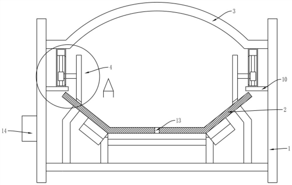
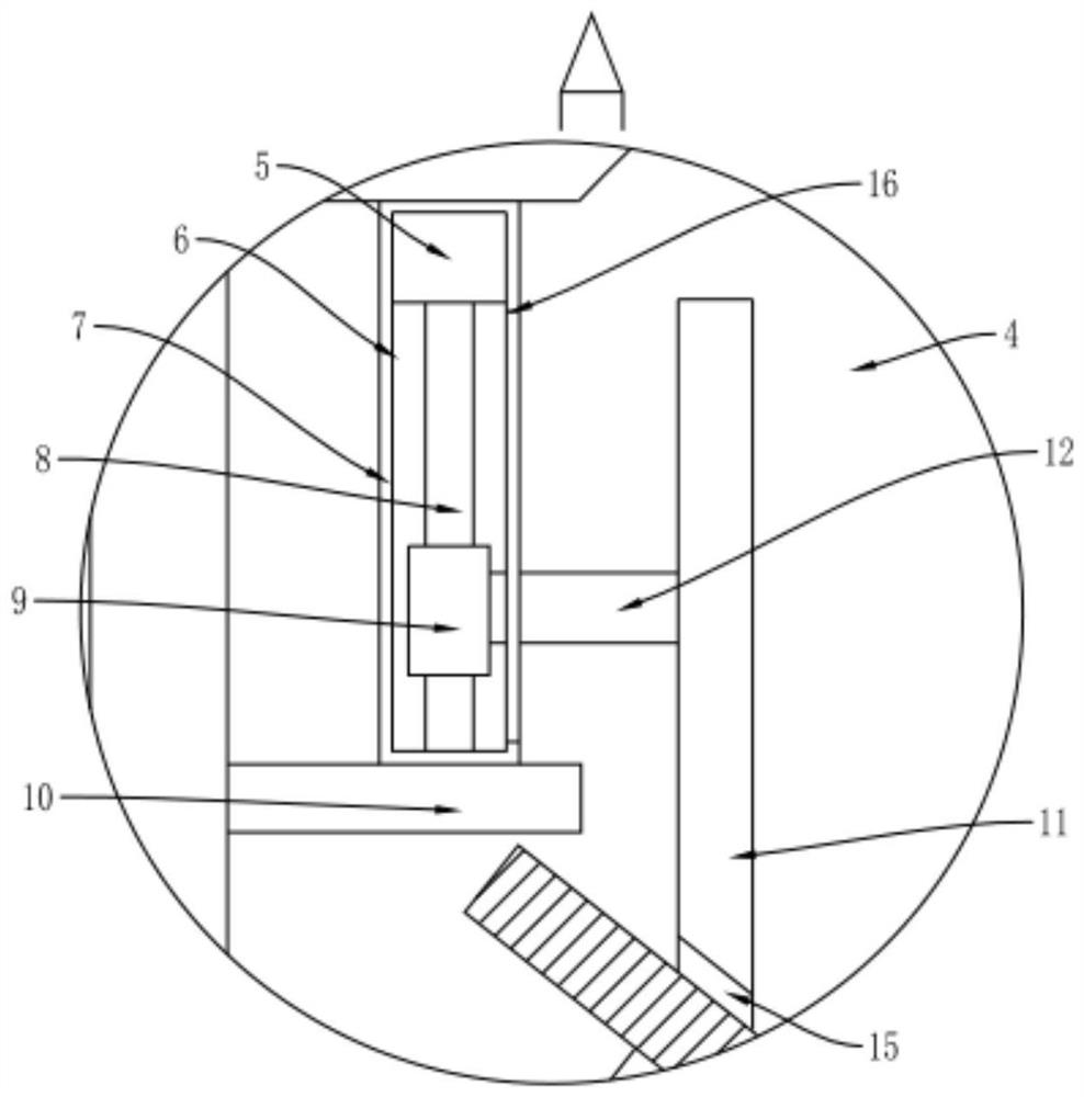
The invention discloses an automatic lifting guide chute device which comprises a rack, a conveying belt, an upper cover plate and a lifting assembly, the conveying belt is arranged on the rack, the upper cover plate is arranged at the top of the rack, and the lifting assembly is close to the conveying belt and arranged below the upper cover plate; the lifting assembly comprises a servo motor, a movable cavity, a side plate, a threaded rod, a threaded sleeve block, an outer supporting plate, a material blocking plate and a connecting plate, the outer supporting plate is arranged on the outer side wall of the rack, one end of the side plate is arranged below the upper cover plate, the other end of the side plate is arranged on the outer supporting plate, the movable cavity is formed in the side plate, and the servo motor is arranged below the top wall of the movable cavity. The invention belongs to the technical field of conveying mechanical equipment, and particularly relates to an automatic lifting guide chute device which can automatically adjust the height of a striker plate, so that the striker plate is not in contact with a conveying belt in a no-load state, the abrasion degree of the striker plate and the conveying belt is reduced, the service life of the conveying belt is prolonged, and the production cost is reduced.

Description

technical field [0001] The invention belongs to the technical field of conveying machinery and equipment, in particular to an automatic lifting and lowering guide chute device. Background technique [0002] The belt conveyor is the abbreviation of the belt conveyor. The belt conveyor uses the continuous or intermittent motion of the conveyor belt to transport various items of different weights, which can not only transport various bulk materials, but also transport various cartons, packaging bags, etc. Large shipments, versatile. [0003] In the existing belt conveyor equipped with a guide groove, no matter the belt is running under heavy load or no load, the baffle plate is in a running friction state with the conveying belt, which will cause damage to the belt and the baffle plate, and greatly reduce the belt speed. the service life and increase the production cost. SUMMARY OF THE INVENTION [0004] In order to solve the above problems, the present invention provides a...

Claims


Application Information

Patent Timeline
IPC IPC(8): B65G21/20B65G43/08B65G15/00
CPCB65G21/2081B65G43/08B65G15/00
Inventor 唐策赵宸王磊
Owner 沈阳金鼎电科环境工程有限公司
Learn More