
Protective oral cavity opener

An opener and oral technology, which is applied in the directions of oral mirrors, stereotaxic surgical instruments, medical science, etc., can solve the problems of danger, closed teeth bite the hands of medical staff, bite the hands of medical staff, etc., to increase elasticity, The effect of preventing cross infection and improving usability

Pending Publication Date: 2022-08-09
菏泽家政职业学院
View PDF0 Cites 0 Cited by
  • Summary
  • Abstract
  • Description
  • Claims
  • Application Information

AI Technical Summary

Problems solved by technology

[0002] Generally, when medical personnel treat the patient's oral cavity, teeth or throat, the patient has to open his mouth wide. After a long time, the patient's mouth drools, mainly because the masseter muscles are tense, and the speed of salivation increases. It may be necessary to rinse the mouth many times and feel tired. It is easy to bite the hand of the medical staff when the mouth is suddenly closed due to pain or tension, especially when the mouth is under local anesthesia, the patient loses control, and often the muscle tension causes the sudden closure of the mouth and the teeth bite the hand of the medical staff, causing danger, or due to oral muscle Insufficient supporting force, resulting in poor field of vision for the doctor to operate. At this time, the patient's mouth needs to be opened with the help of an oral speculum
[0003] Most of the original oral speculum needs to be placed in the patient's mouth. In this way, not only the opening angle of the patient must be large enough during use, but also block the field of vision, resulting in a limited working range of the medical staff, which in turn affects the operation of the medical staff.

Method used


Image

  • Protective oral cavity opener
  • Protective oral cavity opener
  • Protective oral cavity opener

Examples


Embodiment

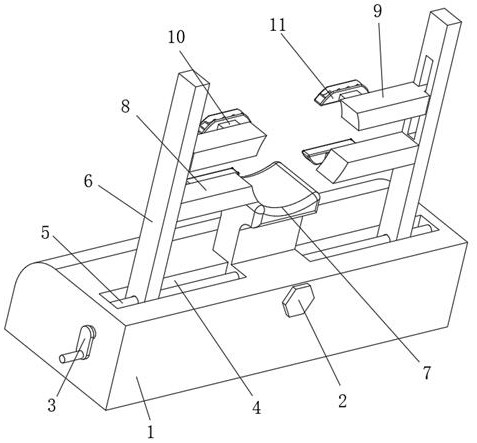
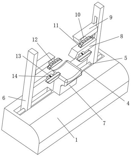
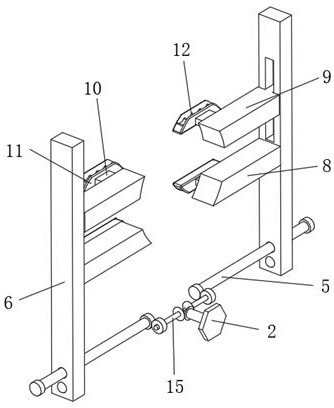
[0028] see figure 1 -7, the present invention provides the following technical solutions: a protective oral dilator, comprising a base 1, one end of the base 1 is provided with a No. 1 handle 2 for transmission, the other end is provided with a No. 2 handle 3 for transmission, and the upper end is provided with a No. The sliding groove 4 for the limit sliding of the connecting frame 6 is provided with a sliding rod 5 for transmission. The base 1 is connected with the connecting frame 6 through the sliding rod 5. The lower support block 8 is also provided with a rectangular groove for the limit sliding of the upper support block 9. The connecting frame 6 is connected with the upper support block 9 through the rectangular groove. The block 10 is positioned and connected with a rectangular groove, and the rectangular groove is provided with a limit groove for the limited engagement of the sliding block 22. The lower support block 8 and the upper support block 9 are connected to t...


PUM


Abstract

The invention belongs to the technical field of oral cavity opening devices, and particularly relates to a protective oral cavity opening device which comprises a base, a first handle used for transmission is arranged at one end of the base, a second handle used for transmission is arranged at the other end of the base, a sliding groove used for limiting sliding of a connecting frame is formed in the upper end of the base, and a sliding rod used for transmission is arranged in the sliding groove. Through the arrangement of an upper supporting block, the upper supporting block is driven to slide in a rectangular groove in the upper end of a connecting frame through transmission of a second handle, so that the supporting distance between the upper supporting block and a lower supporting block is adjusted, and then the opening size of the oral cavity of a patient is adjusted; and therefore, the clamping condition of the sliding block and the rectangular grooves in the lower supporting block and the upper supporting block is controlled, fixing and dismounting of the connecting block and the lower supporting block and the upper supporting block are facilitated, then the limiting sleeve is conveniently taken down, the flexible pad is cleaned and disinfected, and cross infection of the limiting sleeve in the using process is effectively prevented.

Description

technical field [0001] The invention belongs to the technical field of oral dilators, and in particular relates to a protective oral dilator. Background technique [0002] Generally, when medical staff treat the oral teeth or throat of the patient, the patient has to open the mouth wide. After a long time, the patient's mouth is full of water. The main reason is that the masseter muscle is tense and the saliva secretion speed increases. It may be necessary to rinse the mouth many times and feel very tired. It is easy to bite the hand of the medical staff when the mouth is suddenly closed due to pain or tension, especially when the oral cavity is under local anesthesia. Insufficient support force results in poor vision of the doctor's operation. At this time, the patient's mouth needs to be opened with the help of a mouth opener. [0003] Most of the original oral openers need to be placed in the patient's mouth. In this way, during use, not only the patient's opening angle ...

Claims


Application Information

Patent Timeline
IPC IPC(8): A61B1/24A61B90/16A61C19/06
CPCA61B1/24A61B90/16A61C19/06
Inventor 单长丽黄春静李凌枫黄艳军李言侠
Owner 菏泽家政职业学院
Learn More