
Hall rocker knob switch

A technology of knob switch and rocker, which is applied in the field of Hall rocker knob switch, can solve the problems of single function, poor experience effect, unable to meet more needs of user functions, etc., and achieve the effect of good hand feeling

Pending Publication Date: 2022-08-05
DONGGUAN CITY KAIHUA ELECTRONICS
View PDF0 Cites 0 Cited by
  • Summary
  • Abstract
  • Description
  • Claims
  • Application Information

AI Technical Summary

Problems solved by technology

[0003] (1) The function is single, unable to meet the needs of users for more functions, and the experience effect is poor;
[0004] (2) The internal structure is complex, and to realize a certain function, multiple sensors or a combination of sensors are required to realize

Method used


Image

  • Hall rocker knob switch
  • Hall rocker knob switch
  • Hall rocker knob switch

Examples


Embodiment 1

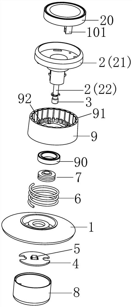
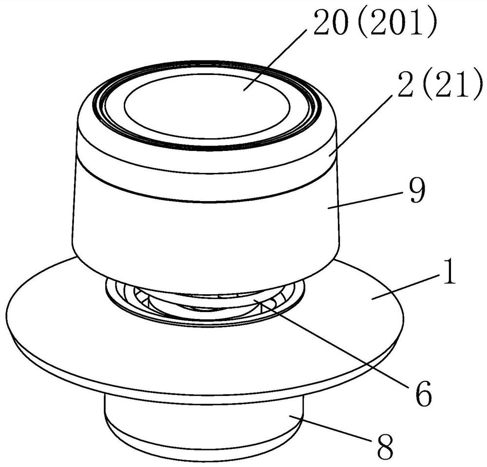
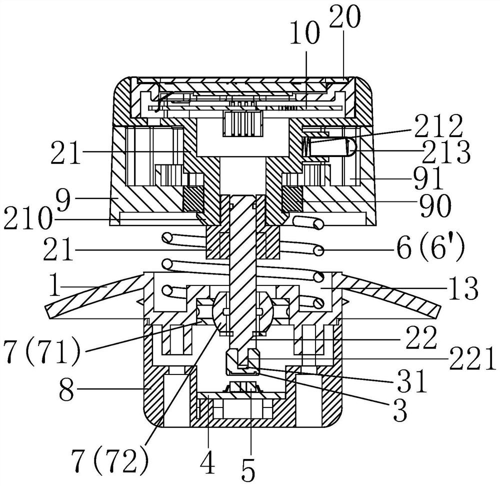
[0045] Please refer to Figure 1 to Figure 4 , this embodiment provides a Hall rocker knob switch, including a base 1, a rocking component 2 disposed on the base 1, a magnet 3 linked with the rocking component 2, a master control PCB board 4, A Hall chip 5 disposed on the master control PCB board 4 and located below the magnet 3, and a reset member 6 for driving the shaking assembly 2 to reset, wherein the shaking assembly 2 drives the magnet 3 to shake to change the Hall chip 5 The induced magnetic flux, thereby outputting different signals. Specifically, in the static state, the magnetic field lines emitted by the magnet 3 penetrate the Hall chip 5, and when the shaking assembly 2 drives the magnet 3 to shake, the number of magnetic field lines emitted by the magnet 3 penetrating the Hall chip 5 will occur. If it changes, the magnetic flux sensed by the Hall chip 5 will change, so that the Hall chip 5 can output different signals, and different signals can define different ...

Embodiment 2

[0064] The main difference between this embodiment and the first embodiment is: Figures 10 to 13 As shown, a second rotating seat 9' is arranged on the periphery of the rocker 21, and a contact spring 91' is arranged on the second rotating seat 9'; 4. A second upper PCB board 10' that is electrically connected, a conductive spring 101' electrically connected to the second upper PCB 10' is provided on the second upper PCB 10', and the contact spring 91' is connected to the second upper PCB 10'. The conducting spring 101' contacts. When the second rotating base 9' is rotated, the contact spring 91' is driven to slide in contact with the conductive spring 101', so as to form an encoder that can rotate 360° and output switch signals.

[0065] Specifically, the second upper PCB board 10 ′ is electrically connected with the master control PCB board 4 through a cable.

[0066] Specifically, as Figure 14 and Figure 15 As shown, the conductive elastic sheet 101' has three conduc...


PUM


Abstract

The invention discloses a Hall rocker knob switch, which comprises a base, a rocking assembly arranged on the base, a magnet linked with the rocking assembly, a master control PCB (Printed Circuit Board), a Hall chip arranged on the master control PCB and positioned below the magnet, and a reset piece used for driving the rocking assembly to reset, and the magnetic flux sensed by the Hall chip is changed, so that different signals are output. According to the Hall rocker knob switch provided by the invention, a 360-degree switch signal shaking function, a switch signal confirmation function and a 360-degree switch signal rotation function can be realized, the functions are multiple, the structure is simplified, and the user experience effect is good.

Description

technical field [0001] The invention relates to a knob switch, in particular to a Hall rocker knob switch. Background technique [0002] In the existing rotary switch, there are the following two shortcomings: [0003] (1) The function is single, unable to meet the user's more needs for functions, and the experience effect is poor; [0004] (2) The internal structure is complex, and to achieve a certain function, multiple sensors or sensor combinations are required to achieve it. SUMMARY OF THE INVENTION [0005] In view of the above deficiencies, the purpose of the present invention is to provide a Hall rocker knob switch, which can realize the 360° rocking switch signal function, the press confirmation switch signal function and the 360° rotary switch signal function, with multiple functions, simplified structure, and user experience. Works well. [0006] The technical scheme that the present invention adopts to achieve the above purpose is: [0007] A Hall rocker kn...

Claims


Application Information

Patent Timeline
Patent Type & Authority Applications(China)
IPC IPC(8): H03K17/90
CPCH03K17/90
Inventor 吴福喜卢海成
Owner DONGGUAN CITY KAIHUA ELECTRONICS
Learn More