DC1500V non-polar magnetic quenching type DC isolating switch

A DC isolating switch and arc-extinguishing technology, applied in electric switches, air switch parts, electrical components, etc., can solve the problem of difficulty in extinguishing the arc, and achieve the advantages of increasing arc voltage, good arc-extinguishing effect and reducing production costs. Effect

Pending Publication Date: 2022-08-05
浙江金莱勒电气有限公司
View PDF0 Cites 0 Cited by
  • Summary
  • Abstract
  • Description
  • Claims
  • Application Information

AI Technical Summary

Problems solved by technology

[0004] Therefore, the technical problem to be solved by the present invention is to overcome the defect that the arc is difficult to extinguish under high voltage in the DC isolating switch in the prior art, thereby providing a DC1500V non-polarity magnetic blowout type DC isolating switch that is easy to extinguish the arc

Method used


Image

  • DC1500V non-polar magnetic quenching type DC isolating switch
  • DC1500V non-polar magnetic quenching type DC isolating switch
  • DC1500V non-polar magnetic quenching type DC isolating switch

Examples


Embodiment

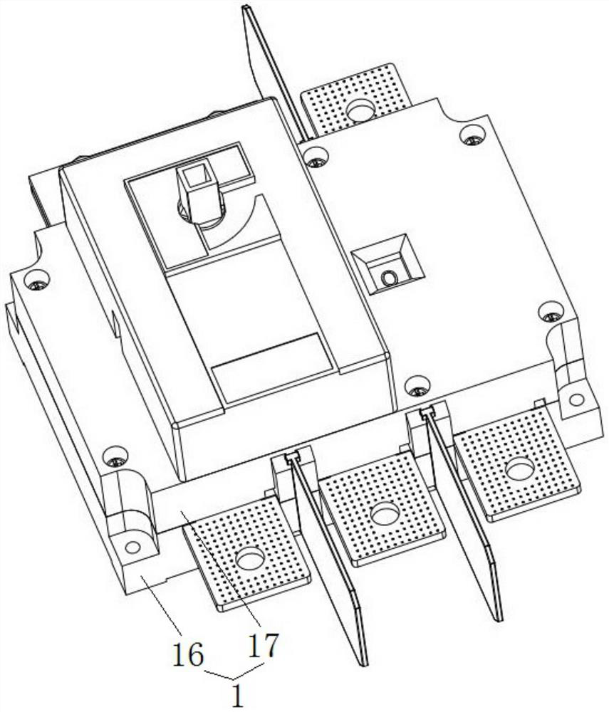
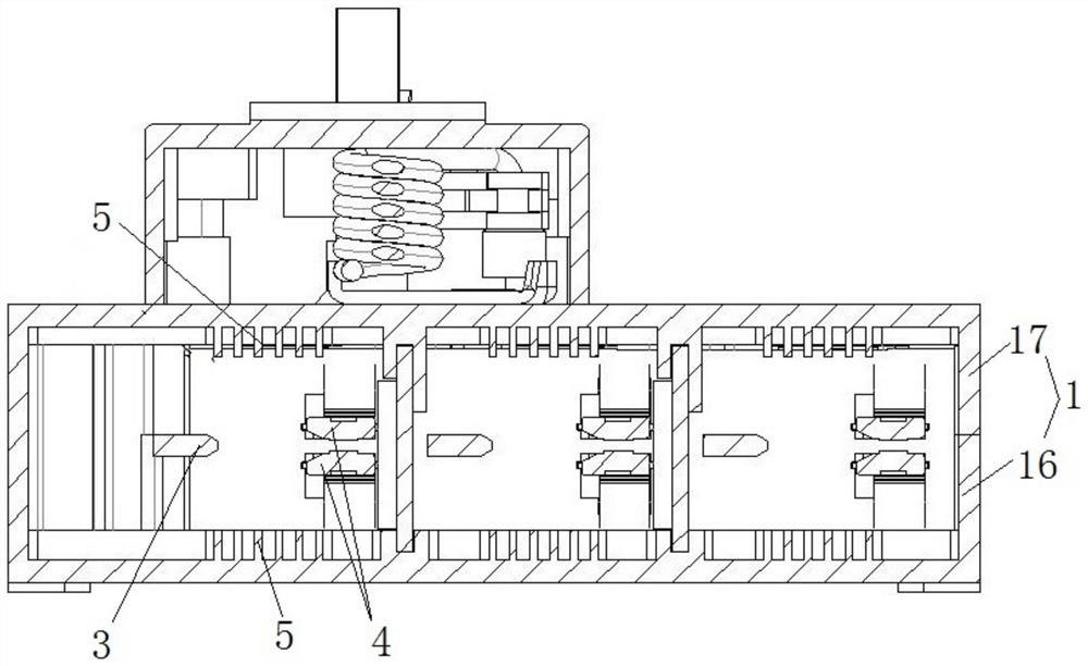
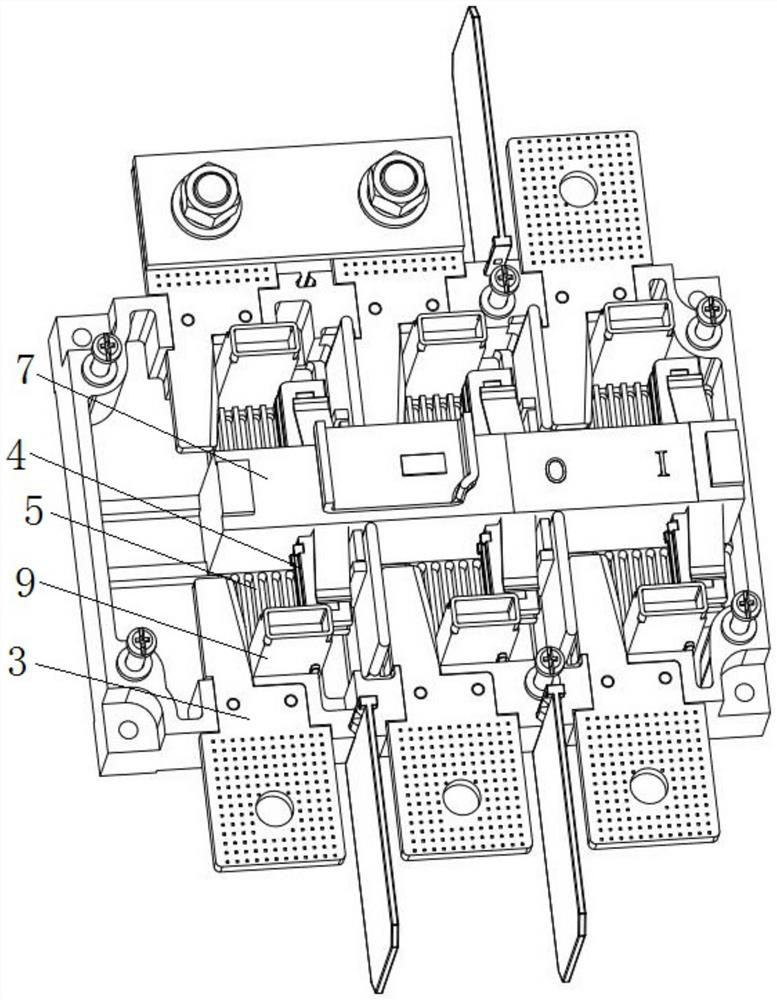
[0038] This embodiment provides a DC1500V non -polar magnetic blowout extinguishing DC isolated switch, such as figure 1 Show, including switching items 1. The contact system, arc extinguishing area 5 and magnetic parts 6.

[0039] Switch body 1, such as figure 2 It shows the cover plate 17 and base 16 of the upper and lower buckle settings, the inner surface of the cover plate 17 and the base of the base 16, respectively. There is a static contact 3 between the area 5. like Figure 5 and 6 Show, the base 16 and the cover plate 17 are formed on the installation slot inserted in the installation bracket 9. In this embodiment, the arc extinguishing region 5 is formed on the switch body 1 through injection molding. by Figure 10 and 11 For example, according to the Apeli formula F = BIL, the magnetic field direction of magnetic parts 6 is perpendicular to the direction of the current I. The arc 18 moves to the base 16 direction (that is, down) under the action of the magnetic field for...


PUM


Abstract

The invention provides a DC 1500V non-polar magnetic quenching type DC isolation switch. The DC isolation switch comprises a switch body; the contact system is arranged on the switch body and comprises a static contact and a moving contact which is in contact connection with the static contact or is separated from the static contact; the arc extinguishing area is provided with arc extinguishing ribs at two sides and is arranged on the switch body; and the magnetic piece is arranged on the switch body and is suitable for blowing electric arcs generated in the opening and closing process of the moving contact and the static contact to the arc extinguishing rib area. By arranging the arc extinguishing rib area, the arc can be segmented, the arc voltage can be increased, the arc can be quickly extinguished, and the switch is suitable for being used in DC1500V.

Description

Technical field [0001] The invention involves the field of DC separation technology, which specifically involves a DC1500V non -polar magnetic blowout extinguishing DC isolation. Background technique [0002] DC isolated switch is used in the power distribution equipment of industrial enterprises for non -frequently connecting and segregated circuits and electrical isolation. It is widely used in power distribution systems and automation systems of construction, power, petrochemical and other industries. [0003] The existing DC isolation is mainly used to connect the loop control of lower voltage and lower power. With the improvement of the voltage, the arc generated during the switching process is becoming more and more difficult to extinguish. It seriously restricts the DC isolation isolation. Development in the field of higher voltage use. Invention content [0004] Therefore, the technical problem to be solved by the present invention is to overcome the deficiencies that ar...

Claims


Application Information

Patent Timeline
IPC IPC(8): H01H9/34H01H9/44H01H31/02
CPCH01H9/34H01H9/443H01H31/02
Inventor 陈浩范林何业勇田纪国郑剑男
Owner 浙江金莱勒电气有限公司
Why Eureka
Try Eureka