Modeling-following double-function multiplexing thick-wall part optical system and vehicle lamp

An optical system, dual-function technology, applied in the direction of headlights, optical signals, semiconductor devices of light-emitting elements, etc., can solve the problems of optical effect defects, space difficulty of headlights, low precision and flexibility, etc., and achieve uniform lighting effect. , the shape is flexible and the effect of high light output efficiency

Pending Publication Date: 2022-08-05
MAGNETI MARELLI AUTOMOTIVE COMPONENTS WUHU
View PDF1 Cites 0 Cited by
  • Summary
  • Abstract
  • Description
  • Claims
  • Application Information

AI Technical Summary

Problems solved by technology

[0002] In the past, the thick-walled parts system had to achieve two functions multiplexing. In most cases, two different LEDs used the same light input system. Considering the actual PCB circuit design and the influence of the heat dissipation performance of the LED itself on the working conditions of the LED , the distance between the LEDs should not be too small, the two LEDs need to be placed out of focus, that is, they are not at the optical focus when the light entering system is designed, so that the light utilization efficiency of each LED is not high, because the light of the LED passes through the entering After the optical system, the light is not completely parallel in the thick-walled parts, and the defocused LEDs have uneven lighting effects when lighting up the thick-walled parts
[0003] The improved technology of the existing technology is to reuse two functions in one area, and use two paraboloids to perform two functions. However, when the light emitted by the parabola enters the second parabola, the light will converge twice. The lighting effect on the final lighting surface will be uneven, and there will be bright spots with bright spots in the middle and dark spots on both sides. The uniformity will be greatly affected, and the paraboloid is a whole, so it is not easy to control the light pattern, precision and flexibility as a whole. Low
[0004] In addition, the existing technology, including the above-mentioned parabolic surface multiplexing system, cannot achieve a conformal and highly flexible design. In fact, the current development trend of car lights is that the shape is becoming more and more narrow, complex, inclined, and large-angle. , if the existing technology needs to deal with various complex shapes, there must be problems in the design of the optical path in order to meet the light energy emitted along the shape surface to the direction of the test position, so that the optical path design cannot be guaranteed to be similar or the same, resulting in defects in optical effects. In addition, the size of the optical unit of the optical system It will inevitably increase, which will not only lead to parts size and cost problems, but also bring great difficulties to the increasingly narrow space of car lights, such as assembly difficulty, the adjustment range of the adjustment system will be limited and interfere with other parts, and thermal problems Difficult to alleviate, etc., when multi-functional functions are required, this problem will be multiplied, which will bring great difficulties to the design of car lights

Method used


Image

  • Modeling-following double-function multiplexing thick-wall part optical system and vehicle lamp
  • Modeling-following double-function multiplexing thick-wall part optical system and vehicle lamp
  • Modeling-following double-function multiplexing thick-wall part optical system and vehicle lamp

Examples


Embodiment 1

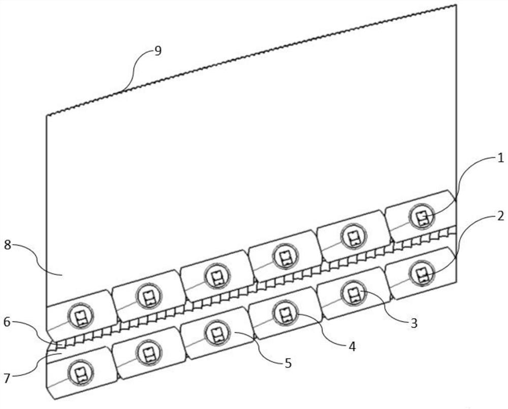
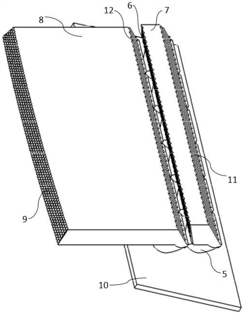
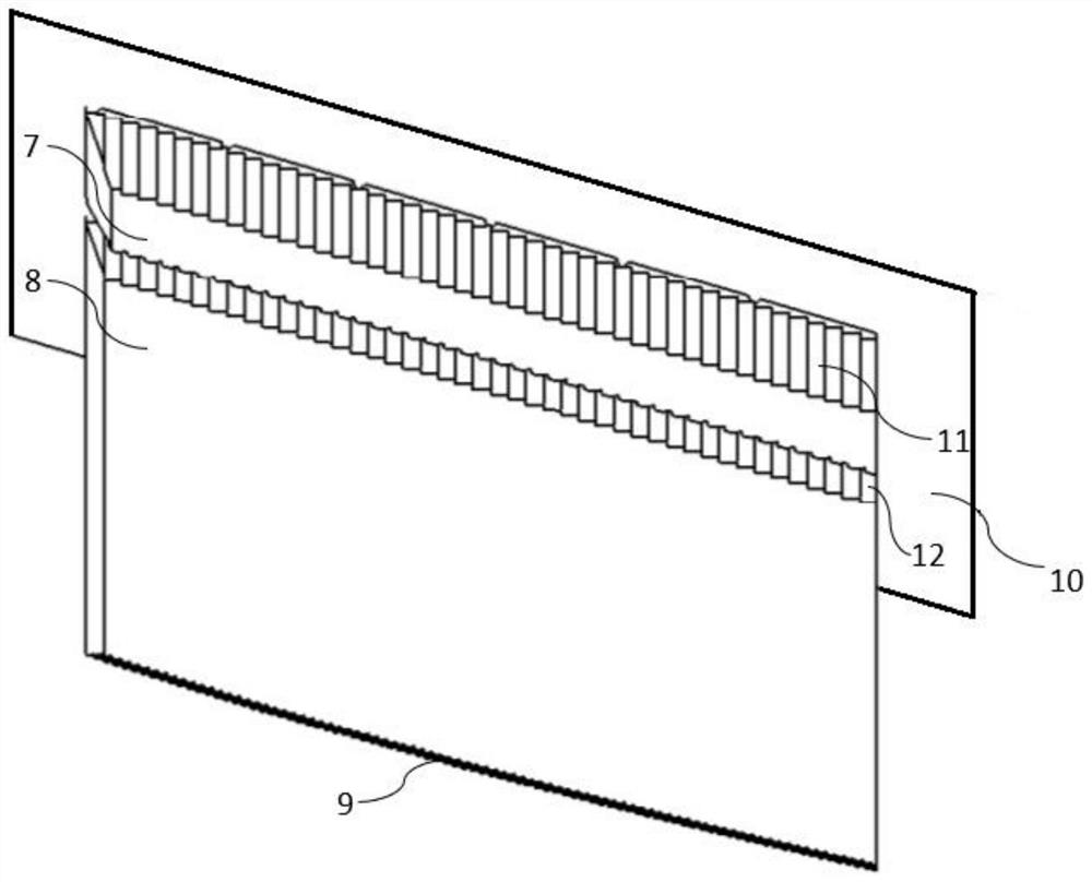
[0051] The present invention provides a dual-function multiplexing thick-walled optical system following modeling, such as Figure 1-13 As mentioned above, it includes a first light source 1 , a second light source 2 , a first thick-walled member 7 , a second thick-walled member 8 , a light entry system and a PCB board 10 . The light emission angle of the first light source 1 and the second light source 2 is 120°. The first light source 1 and the second light source 2 are respectively connected to the PCB board 10. The first light source 1 corresponds to the second thick-walled member 8, and the second light source 2. Corresponding to the first thick-walled member 7, a gap is provided between the first thick-walled member 7 and the second thick-walled member 8. The light entry system is respectively connected to the first thick-walled part 7 and the second thick-walled part 8. The light entry system includes an incident refracting collimating surface 3, an incident refracting ...

Embodiment 2

[0063] The invention also provides a vehicle lamp, which includes a dual-function multiplexed thick-walled optical system following the modeling.


PUM


Abstract

The invention relates to the technical field of vehicle lamps, and provides a modeling following double-function multiplexing thick-wall part optical system and a vehicle lamp, the modeling following double-function multiplexing thick-wall part optical system comprises a first light source, a second light source, a first thick-wall part, a second thick-wall part and a PCB, the first light source and the second light source are connected to the PCB, the first light source corresponds to the second thick-wall part, and the second light source corresponds to the second thick-wall part. The second light source corresponds to the first thick-wall piece, a first total reflection step face is arranged on the first thick-wall piece, and a second total reflection step face is arranged on the second thick-wall piece. The two thick-wall parts are used for separation, the corresponding light sources with different functions are all located on the focus of the light inlet, the lighting effect is more uniform, the light emitting efficiency is higher, the step-shaped total reflection step face is matched, light rays are always spread along the same angle on the vertical plane and cannot be converged, it is guaranteed that the laws and regulations of all functions of multiplexing are met, and the light emitting efficiency is improved. And meanwhile, the multi-functional shape-following modeling design is realized, the cost and the space are saved, and the beneficial effects are doubled.

Description

technical field [0001] The invention relates to the technical field of vehicle lamps, in particular, to a dual-function multiplexed thick-walled optical system and a vehicle lamp following modeling. Background technique [0002] In the past, the thick-walled part system needs to realize the multiplexing of two functions. In most cases, two different LEDs use the same light entry system. Considering the actual PCB circuit design and the influence of the heat dissipation performance of the LED itself on the working condition of the LED , the distance between the LEDs should not be too small, and both LEDs need to be placed out of focus, that is, they are not on the optical focus of the light entry system design, so the light utilization efficiency of each LED is not high, because the light of the LED passes through the entrance. After the optical system, the light rays in the thick-walled parts are not completely parallel, and the LED after defocusing, when lighting the thick-...

Claims


Application Information

Patent Timeline
IPC IPC(8): F21S41/20F21S41/30F21S41/148F21S43/14F21S43/20F21S43/30F21W107/10F21Y115/10
CPCF21S41/20F21S41/30F21S41/148F21S43/20F21S43/30F21S43/14F21W2107/10F21Y2115/10
Inventor 江璐芸
Owner MAGNETI MARELLI AUTOMOTIVE COMPONENTS WUHU
Why Eureka
Try Eureka