Adjustable combined peristaltic pump

A peristaltic pump and adjustable technology, applied in the field of peristaltic pumps, can solve the problems of inconvenient adjustment of the outlet pressure, shortened service life of the hose, inconvenient control, etc., and achieve the effects of easy operation, extended service life, and convenient and precise adjustment.

Active Publication Date: 2022-08-05
保定齐力恒流泵有限公司
View PDF17 Cites 0 Cited by
  • Summary
  • Abstract
  • Description
  • Claims
  • Application Information

AI Technical Summary

Problems solved by technology

[0004] However, when in use, the wear and tear on the hose is relatively large, resulting in a reduction in the service life of the hose, and when in use, it is inconvenient to adjust the pressure of the outlet liquid, and the adjustment is less accurate and not easy Easy to control

Method used


Image

  • Adjustable combined peristaltic pump
  • Adjustable combined peristaltic pump
  • Adjustable combined peristaltic pump

Examples


Embodiment 1

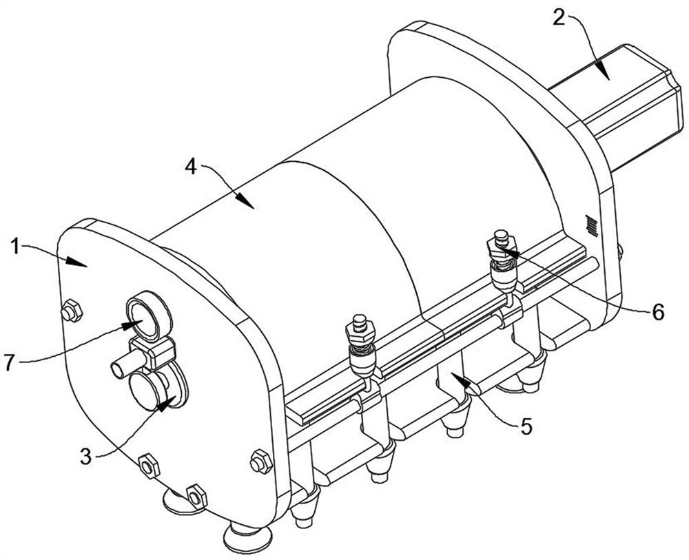
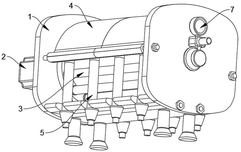
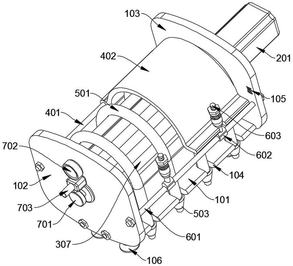
[0029] see Figure 1-9 As shown, an adjustable combined peristaltic pump includes a frame assembly 1, a drive assembly 2 is fixedly installed on one side of the frame assembly 1, and a pump head roller assembly 3 is fixedly installed inside the frame assembly 1, and the output of the drive assembly 2 The end is plugged into the pump head roller assembly 3, and the drive assembly 2 drives the pump head roller assembly 3. Between the interior of the frame assembly 1 and above the pump head roller assembly 3, a pressing and holding assembly 4 is rotatably installed. , the middle position of the frame assembly 1 is evenly plugged with four hose assemblies 5, and the hose assemblies 5 bypass the pump head roller assembly 3, and the middle position of the hose assembly 5 is located between the pump head roller assembly 3 and the pressure Between the holding components 4 and the other side between the frame components 1, an adjusting component 6 is fixedly installed, and the upper en...

Embodiment 2

[0036] see Figure 1-10 As shown, an adjustable combined peristaltic pump includes a frame assembly 1, a drive assembly 2 is fixedly installed on one side of the frame assembly 1, and a pump head roller assembly 3 is fixedly installed inside the frame assembly 1, and the output of the drive assembly 2 The end is plugged into the pump head roller assembly 3, and the drive assembly 2 drives the pump head roller assembly 3. Between the interior of the frame assembly 1 and above the pump head roller assembly 3, a pressing and holding assembly 4 is rotatably installed. , the middle position of the frame assembly 1 is evenly plugged with four hose assemblies 5, and the hose assemblies 5 bypass the pump head roller assembly 3, and the middle position of the hose assembly 5 is located between the pump head roller assembly 3 and the pressure Between the holding components 4 and the other side between the frame components 1, an adjusting component 6 is fixedly installed, and the upper e...


PUM


Abstract

The invention relates to the technical field of peristaltic pumps, in particular to an adjustable combined peristaltic pump which comprises a frame assembly, a driving assembly is fixedly mounted on one side of the frame assembly, a pump head roller assembly is fixedly mounted in the frame assembly, and a pressing assembly is rotationally mounted above the inner portion of the frame assembly. Four hose assemblies are evenly inserted in the middle of each frame assembly, an adjusting assembly is fixedly installed on the other side between the frame assemblies, an inner adjusting assembly is fixedly installed on one side of the outer portion of each frame assembly, pressing of the hose assemblies by the pressing assemblies is adjusted through adjusting nuts and the inner adjusting assemblies, and the strength of air pressure in the knitted pipe sleeve is adjusted. According to the device, the pressing force of the hose assembly is conveniently and accurately adjusted, then the output pressure is conveniently and accurately adjusted, the multiple knitted pipe sleeves are arranged, the liquid outlet pulse is effectively reduced, the rotating speed of the stepping motor is reduced, the pressing rigidity of a water passing pipe is reduced through the spring and the knitted hose, and the service life is prolonged.

Description

technical field [0001] The invention relates to a peristaltic pump, in particular to an adjustable combined peristaltic pump, which belongs to the technical field of peristaltic pumps. Background technique [0002] The peristaltic pump is like squeezing a fluid-filled hose with fingers. As the finger slides forward, the fluid in the tube moves forward. This is also the principle of the peristaltic pump. The fingers are replaced by rollers, and the elastic delivery hose of the pump is alternately squeezed. Pressure and release to pump fluid, just like squeezing a hose with two fingers, with the movement of the fingers, negative pressure is formed in the tube, and the liquid flows with it, which is widely used in many fields, such as the chemical industry; mining; , metallurgical industry; paper industry; paint and coating industry; food industry; ceramic industry; petroleum industry; water treatment industry; pharmaceutical industry; medical device industry. Installed, such ...

Claims


Application Information

Patent Timeline
Patent Type & Authority Applications(China)
IPC IPC(8): F04B43/12F04B17/03F04B53/22F04B53/00
CPCF04B43/1269F04B17/03F04B53/22F04B53/00
Inventor 刘伟
Owner 保定齐力恒流泵有限公司
Why Eureka
Try Eureka