Robot joint combined sealing structure

A robot joint and combined sealing technology, which is applied to manipulators, program-controlled manipulators, manufacturing tools, etc., can solve the problems of joint seal reliability and installation difficulties, and achieve the effects of long service life, consistency and reliability

Pending Publication Date: 2022-08-05
NANJING ESTUN ROBOTICS CO LTD
View PDF1 Cites 0 Cited by
  • Summary
  • Abstract
  • Description
  • Claims
  • Application Information

AI Technical Summary

Problems solved by technology

[0004] The purpose of the present invention is to overcome the technical defects existing in the prior art, provide a combined sealing structure of robot joints, and solve the problems of reliability and installation difficulties of existing joint seals

Method used


Image

  • Robot joint combined sealing structure
  • Robot joint combined sealing structure
  • Robot joint combined sealing structure

Examples


Embodiment 1

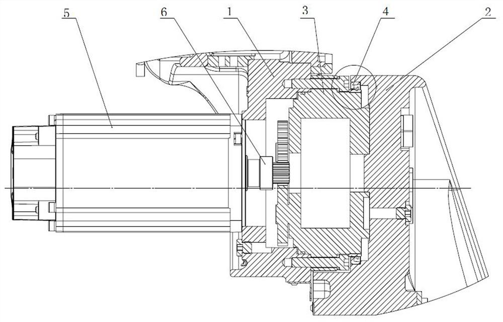
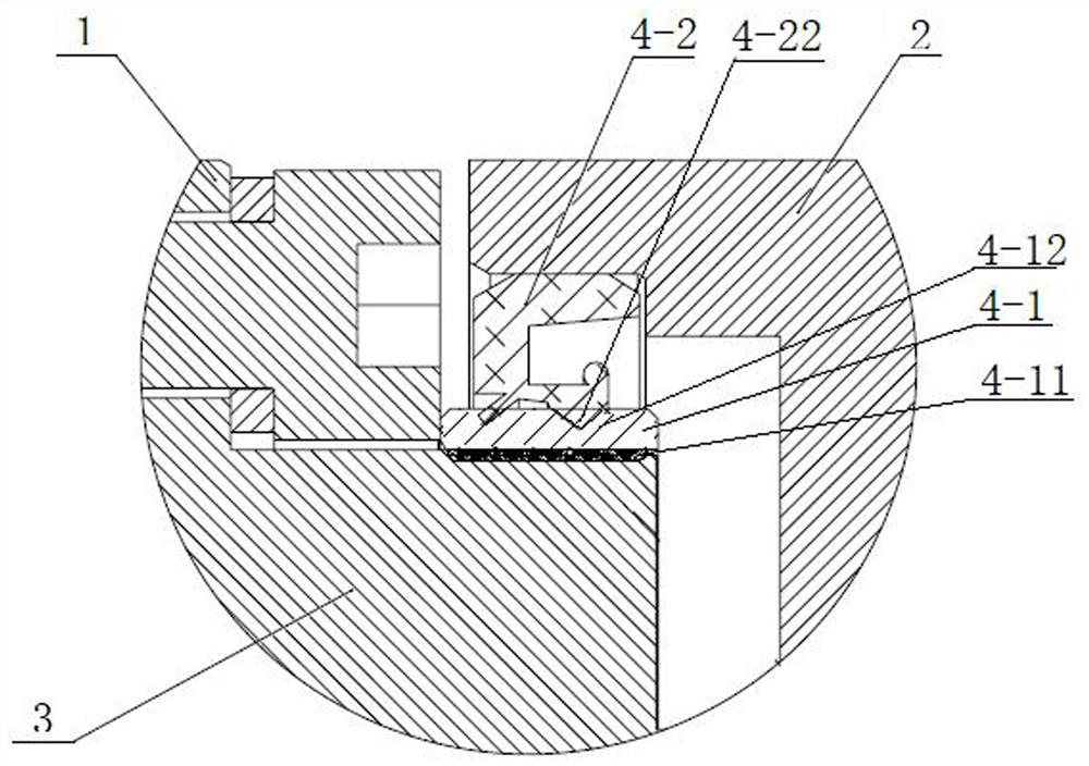
[0029] see Figure 1 to Figure 2 , figure 1 Shown is a typical robot joint structure, which is provided with a first moving member 1, a second moving member 2, a reduction gear 3, a joint combined oil seal 4, a motor 5, and a reduction gear input gear 6. The motor 5 drives the deceleration device 3 to output and rotate through the deceleration device input gear 6 . The joint combination oil seal 4 is provided between the second moving member 2 and the reduction gear 3 . like figure 2 As shown, the joint combined oil seal 4 includes two parts, a skeleton bushing 4-1 and a sealing ring 4-2. The inner side of the skeleton bushing 4-1 is provided with an elastic sealing ring 4-11, the elastic sealing ring 4-11 and the reduction gear 3 The housing is in static sealing contact. The elastic sealing ring 4-11 is made of elastic sealing material, which can effectively prevent the leakage of grease in the cavity and the entry of external pollutants through the gap between the skele...

Embodiment 2

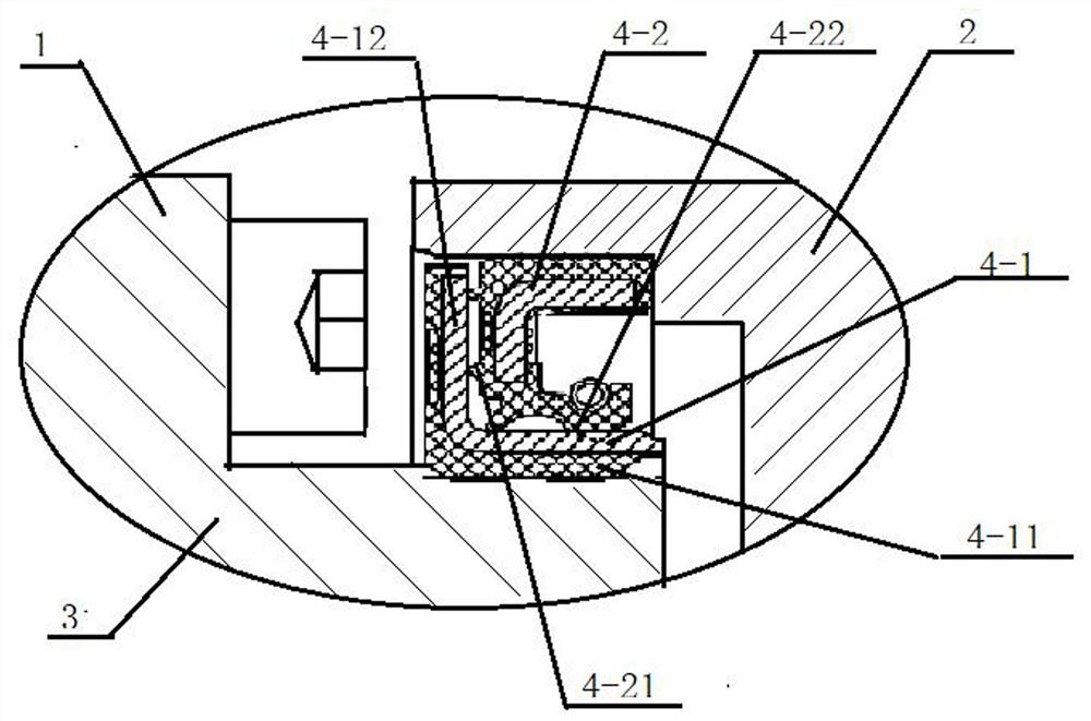
[0033] Basically the same as the embodiment, the difference is that the frame of the frame bushing 4-1 includes the structure of the flange edge 4-12 (such as image 3 shown), an annular end face sealing lip 4-21 is provided on the outer end surface of the sealing ring 4-2, and the end face sealing lip 4-21 is in sealing contact with the flange edge 4-12 of the skeleton bushing to further enhance the sealing effect.

Embodiment 3

[0035] It is basically the same as the embodiment, the difference is that the sealing ring 4-2 adopts the Figure 4 Double main lip skeleton oil seal shown. For the present invention, the sealing ring 4-2 may also be a Y-shaped ring, an A-shaped ring, a B-shaped ring or a C-shaped ring.


PUM


Abstract

The invention discloses a robot joint combined sealing structure which is characterized in that a framework lining of a joint combined oil seal is fixedly mounted on a shell at the output end of a speed reducer, and an elastic sealing ring is arranged between the framework lining and a shell of the speed reducer and is in static sealing contact with the shell of the speed reducer; the sealing ring is fixedly mounted in a sealing ring mounting groove of the second moving component and is in static sealing contact with the second moving component; the framework lining is sleeved with the sealing ring, and sealing is achieved. And a sealing lip on the inner ring surface of the sealing ring is in sealing contact with the circumferential side wall of the outer ring of the framework bushing. The framework lining can also be provided with a flange edge, and the end face sealing lip on the outer end face of the sealing ring is in sealing contact with the flange edge of the framework lining, so that the sealing reliability is improved. The sealing device is good in sealing effect, and can be used in occasions with high requirements for cleanness and high protection grade. The framework lining and the speed reducer are statically sealed, the sealing ring and the joint movement component are statically sealed, the static sealing surface is large, the joint is fixed and reliable during rotation, and follow-up rotation is avoided.

Description

technical field [0001] The invention relates to a sealing structure of a robot joint assembly, which is specifically applied to a relatively rotating joint of a robot, and is arranged on a deceleration device for sealing a cavity between the deceleration device and a robot component. Background technique [0002] With the continuous development of robot technology, some applications will have clean requirements or high protection level requirements for robots. In order to prevent leakage of the robot joints with relative motion, to leak the oil in the joints to the external environment, or to prevent foreign objects from the external environment from entering the interior of the joints, the robots in the prior art often need to add sealing members at the robot joints. . [0003] For example, the Chinese utility model patent "A New Type of Robot Joint Sealing Structure and Protection Robot" (authorized announcement number: CN215358521U), the robot joint sealing structure dis...

Claims


Application Information

Patent Timeline
Patent Type & Authority Applications(China)
IPC IPC(8): B25J17/00B25J9/10
CPCB25J17/00B25J9/10
Inventor 张扬张彦奎张冶吕健耿羚彪党相磊
Owner NANJING ESTUN ROBOTICS CO LTD
Why Eureka
Try Eureka