Fan control method and system
A fan control and fan technology, applied in the field of artificial intelligence, can solve the problems of low control precision and complicated operation of fan speed control, and achieve the effect of improving control accuracy and remote control of fan speed
- Summary
- Abstract
- Description
- Claims
- Application Information
AI Technical Summary
Problems solved by technology
Method used
Image
Examples
Embodiment 1
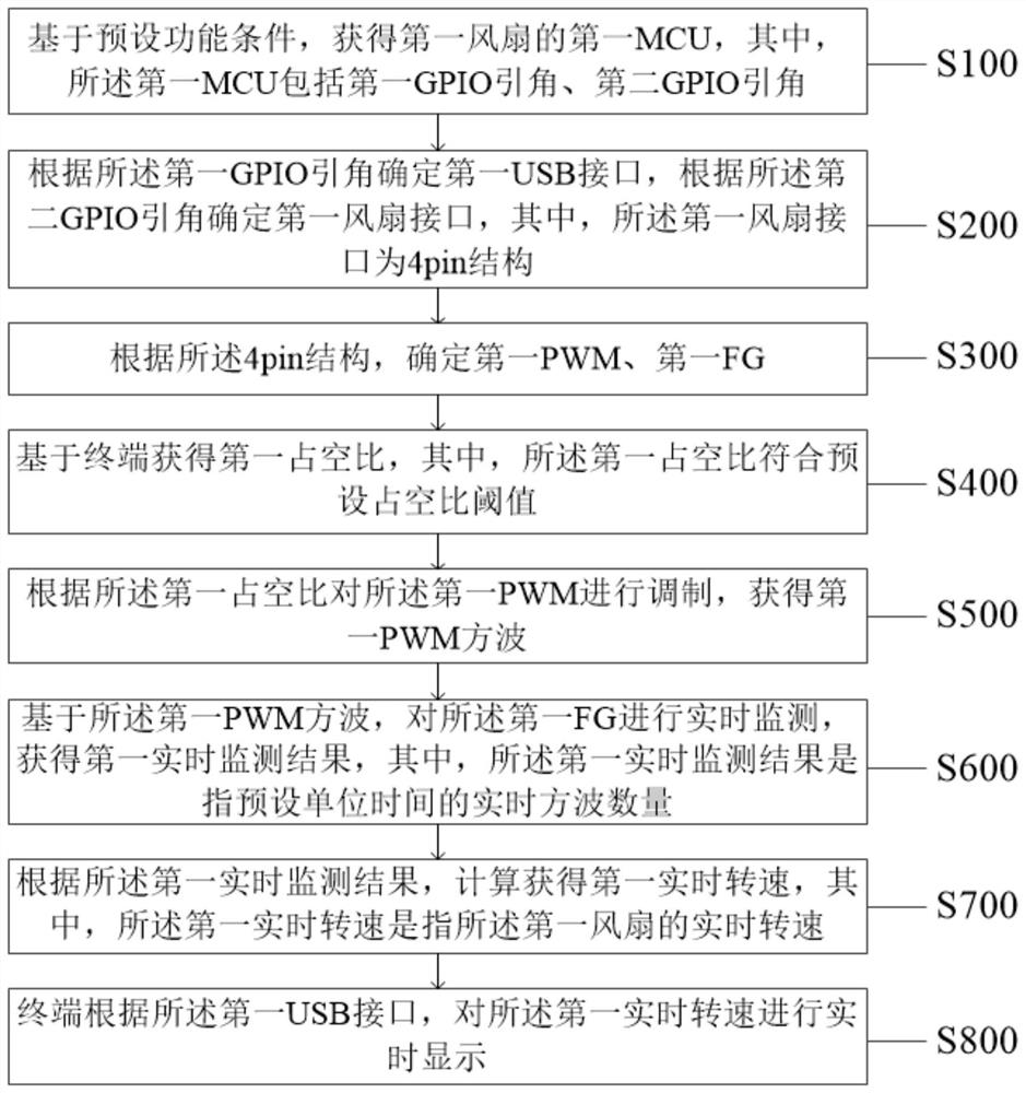
[0033] Please see attached figure 1 , the present application provides a fan control method, wherein the method is applied to a fan control system, and the method specifically includes the following steps:
[0034] Step S100: obtaining a first MCU of the first fan based on a preset functional condition, wherein the first MCU includes a first GPIO lead and a second GPIO lead;
[0035] Further, the preset functional condition refers to the serial port function.
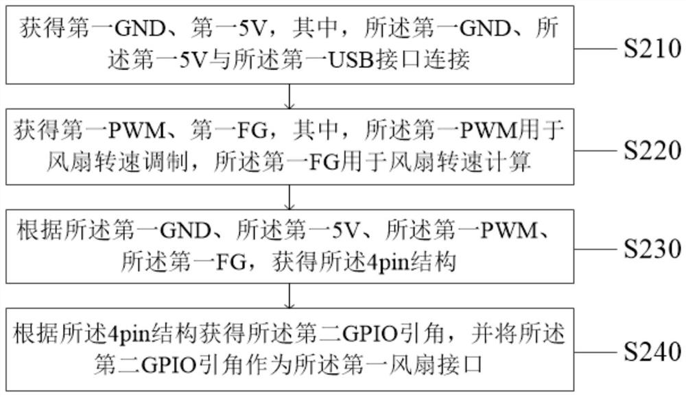
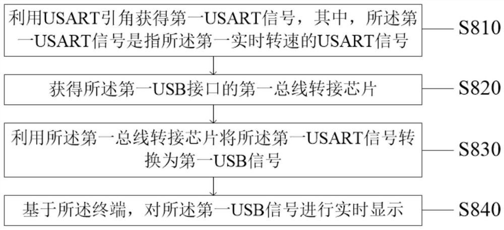
[0036] Specifically, when the fan control method is applied to the fan control system, the fan speed can be precisely modulated through terminal settings, and the accurate fan speed can be determined and displayed in real time through intelligent calculation. The first fan refers to any fan that is to be intelligently controlled by the fan control system. The preset function condition refers to a serial port function, which is a basic function that the first MCU in the first fan should have to use the fan control syst...
Embodiment 2
[0066] like Figure 4 As shown, the present invention discloses a fan control device, the fan control device is used to execute the steps of the method in Embodiment 1, wherein the fan control device includes:
[0067] MCU100, the MCU100 has a serial port function;
[0068] A first GPIO lead 110, the first GPIO lead 110 is set on the MCU 100, and the first GPIO lead 110 is a USB interface, used for powering the fan control device, and reading at the same time Fan speed signal and transmission;
[0069] A second GPIO lead 120, the second GPIO lead 120 is parallel to the first GPIO lead 110, and is also provided on the MCU 100, and the second GPIO lead 120 is used to calculate the fan speed;
[0070] A terminal 200, the terminal 200 is connected to the MCU 100 in communication, and is used to modulate the fan speed, and at the same time, receive and display the fan speed signal transmitted by the first GPIO lead 110 in real time.
[0071] Specifically, the fan control device ...
Embodiment 3
[0074] Based on the same inventive concept as the fan control method in the first embodiment, the present application also provides a fan control system. Please refer to the appendix Figure 5 , the system includes:
[0075] a first obtaining unit 11, the first obtaining unit 11 is configured to obtain a first MCU of the first fan based on a preset functional condition, wherein the first MCU includes a first GPIO lead and a second GPIO lead;
[0076] A first determination unit 12, the first determination unit 12 is configured to determine the first USB interface according to the first GPIO lead angle, and determine the first fan interface according to the second GPIO lead angle, wherein the first fan The interface is 4pin structure;
[0077] a second determination unit 13, the second determination unit 13 is configured to determine the first PWM and the first FG according to the 4pin structure;
[0078] a second obtaining unit 14, the second obtaining unit 14 is configured t...
PUM
 Abstract
Description
Claims
Application Information
 - R&D
- Intellectual Property
- Life Sciences
- Materials
- Tech Scout
- Unparalleled Data Quality
- Higher Quality Content
- 60% Fewer Hallucinations
Browse by: Latest US Patents, China's latest patents, Technical Efficacy Thesaurus, Application Domain, Technology Topic, Popular Technical Reports.
© 2025 PatSnap. All rights reserved.Legal|Privacy policy|Modern Slavery Act Transparency Statement|Sitemap|About US| Contact US: help@patsnap.com


