High-speed motorized spindle thermoelastic deformation simulation method and system based on boundary element model

A high-speed electro-spindle and simulation method technology, applied in the direction of constraint-based CAD, electro-digital data processing, instruments, etc., can solve the problems of unable to give full play to the advantages of the algorithm, large amount of calculation, ignoring the pressure distribution, etc., and achieve simple node division steps. , the effect of strong versatility and improved computing efficiency

Pending Publication Date: 2022-07-29
XI AN JIAOTONG UNIV
View PDF0 Cites 1 Cited by
  • Summary
  • Abstract
  • Description
  • Claims
  • Application Information

AI Technical Summary

Problems solved by technology

The motorized spindle is simplified as an axisymmetric hollow cylinder, and the thermoelastic deformation of the spindle is calculated by the elastic mechanics formula. However, the hollow cylinder model of the spindle built by this method is too simplified, and the influence of uneven pressure distribution and temperature gradient changes on deformation is ignored.
The finite element method can truly respond to the load and temperature distribution, and has been widely used in practical applications. This method constructs the fi

Method used


Image

  • High-speed motorized spindle thermoelastic deformation simulation method and system based on boundary element model
  • High-speed motorized spindle thermoelastic deformation simulation method and system based on boundary element model
  • High-speed motorized spindle thermoelastic deformation simulation method and system based on boundary element model

Examples


Embodiment Construction

[0038] The present invention will be further described below with reference to the accompanying drawings and embodiments.

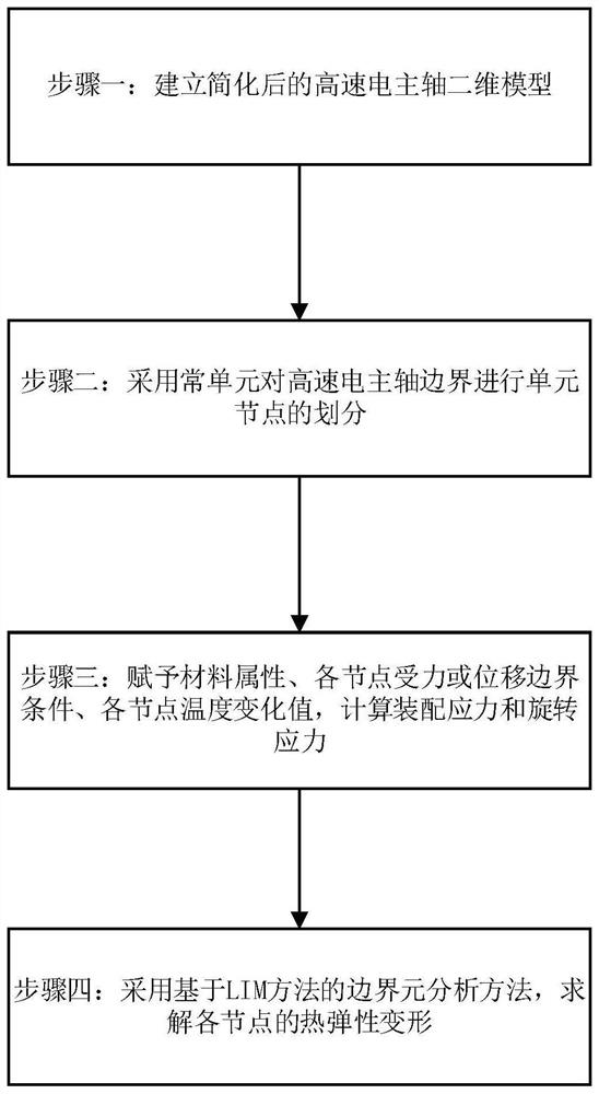
[0039] like figure 1 As shown, a method for simulating thermoelastic deformation of a high-speed motorized spindle based on a boundary element model includes the following steps:

[0040] Step 1: Build a simplified 2D model of the high-speed motorized spindle.

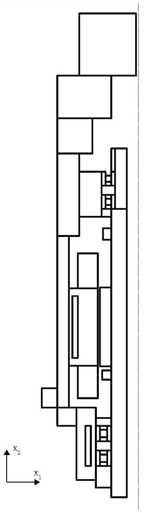
[0041] like figure 2 As shown in the figure, the 1 / 4 plane of the high-speed motorized spindle is intercepted as an axisymmetric two-dimensional model, and the model of the intercepted two-dimensional plane model is simplified, including the detailed features of the high-speed motorized spindle, such as small holes, shallow grooves, tiny bosses, Delete the chamfers, undercuts and transition arcs at the shaft end; delete sensors, wires and sealing rings that are light in weight and do not bear stress; , which are merged with the housing and the main shaft respectively; the built-in motor struct...


PUM


Abstract

The invention discloses a high-speed motorized spindle thermoelastic deformation simulation method and system based on a boundary element model, and the method comprises the steps: intercepting a 1/4 plane of a motorized spindle as a two-dimensional plane model of the high-speed motorized spindle, removing parts and features which can neglect the influence on thermoelastic deformation calculation according to the features of a shaft system, simplifying the model, and calculating the thermoelastic deformation of the motorized spindle. In the simplified two-dimensional plane model, carrying out node division on the boundary of the motorized spindle by adopting a constant unit, constructing a unit model of a motorized spindle boundary element, endowing each part of the motorized spindle with material attributes and boundary conditions, and according to the unit model of the motorized spindle boundary element and the boundary conditions, adopting a boundary element method based on an LIM method, the boundary element method is applied to the modeling and solving process of the thermoelastic deformation of the high-speed motorized spindle, the model universality is improved while the solving precision is guaranteed, and the method is suitable for solving the thermoelastic deformation of various high-speed motorized spindles.

Description

technical field [0001] The invention belongs to the technical field of high-speed electric spindle thermoelastic deformation processing, and particularly relates to a method and system for simulating thermoelastic deformation of a high-speed electric spindle based on a boundary element model. Background technique [0002] During the operation of the high-speed motorized spindle, it will be subjected to the combined effect of static load, external cutting force and thermal load. This comprehensive effect will cause thermoelastic deformation to the structure of the motorized spindle, which will further affect the running accuracy of the high-speed motorized spindle and cause machining errors. Therefore, the calculation of the thermoelastic deformation of the high-speed motorized spindle is one of the key technologies to improve the accuracy of the high-speed motorized spindle. [0003] At present, the hollow cylinder model of the electrospindle and the finite element model are...

Claims


Application Information

Patent Timeline
IPC IPC(8): G06F30/17G06F30/20G06F111/04G06F119/14
CPCG06F30/17G06F30/20G06F2111/04G06F2119/14
Inventor 李小虎展梓荃万少可洪军闫柯
Owner XI AN JIAOTONG UNIV
Why Eureka
Try Eureka