Air purification device for smart home

An air purification device and smart home technology, applied in the field of air purification, can solve problems such as low working efficiency, affecting filtration efficiency, and inability to collect dust, so as to facilitate cleaning and improve work efficiency

Pending Publication Date: 2022-07-29
意之家商业运营海安有限公司
View PDF5 Cites 0 Cited by
  • Summary
  • Abstract
  • Description
  • Claims
  • Application Information

AI Technical Summary

Problems solved by technology

The existing purification device cannot collect the dust accumulated on the filter screen. Too much dust on the surface of the filter screen affects the filtration efficiency. It is not convenient to clean the collected dust. When collecting the dust accumulated on the filter screen surface, the purification device needs to be stopped. Low work efficiency and poor practicability

Method used


Image

  • Air purification device for smart home
  • Air purification device for smart home
  • Air purification device for smart home

Examples


Embodiment 1

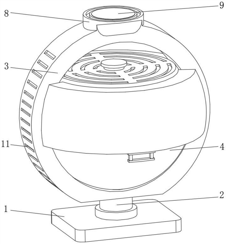
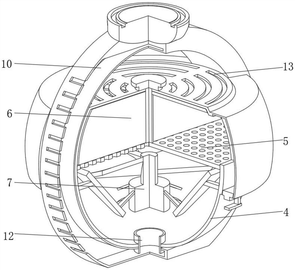
[0028] see Figure 1-Figure 3 , the present invention provides a technical solution: an air purification device for a smart home, comprising a fixed base 1, the top of the fixed base 1 is rotatably connected with a rotating support 2 through a rotating base, and the top of the rotating support 2 is fixedly connected with an annular side plate 3 , the inner side of the annular side plate 3 is fixedly connected with a purification frame 4, the inner wall of the purification frame 4 is fixedly connected with a filter screen 5, the interior of the purification frame 4 is located above the filter screen 5 and a collection device 6 is installed, and the inner wall of the purification frame 4 is located in the filter screen 5. A fan 7 is fixedly connected to the bottom of the net 5 through a support frame, a device block 8 is fixedly connected to the top of the annular side plate 3, a control panel 9 is arranged on the top of the device block 8, and a cavity 10 is symmetrically opened...

Embodiment 2

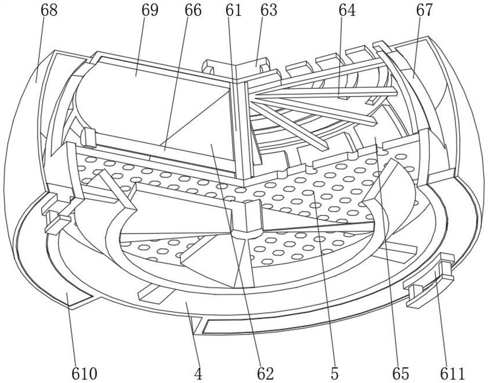
[0036] see Figure 1-Figure 6 , the present invention provides a technical solution: on the basis of the first embodiment, the rolling brush device 66 includes a round tube 661, one end of the round tube 661 is fixedly connected with a rolling column 662, and the outer side of the round tube 661 is evenly opened with a serpentine mouth 663 The inner part of the circular tube 661 is fixedly connected to the limiting column 664, the outer side of the limiting column 664 is evenly installed with a compression spring 665, and the end of the compression spring 665 away from the limiting column 664 is fixedly connected with a serpentine plate 666, and the serpentine plate 666 is far away from the compression A brush head 667 is evenly installed on one side of the spring 665 , and a cleaning device 668 is installed on one side of the rolling column 662 .

[0037] One end of the circular tube 661 away from the rolling column 662 is rotatably connected to the semicircular rotating plat...


PUM


Abstract

The air purification device comprises a fixed base, the top of the fixed base is rotationally connected with a rotating support through a rotating seat, the top of the rotating support is fixedly connected with an annular side plate, the inner side of the annular side plate is fixedly connected with a purification frame, and the inner wall of the purification frame is fixedly connected with a filter screen; and a collecting device is installed at the position, located above the filter screen, in the purifying frame, a draught fan is fixedly connected to the position, located below the filter screen, of the inner wall of the purifying frame through a supporting frame, and a device block is fixedly connected to the top of the annular side plate. According to the air purification device for the smart home, dust accumulated on the filter screen can be collected, the situation that the filtering efficiency is affected by too much dust on the surface of the filter screen is avoided, meanwhile, the collecting frame can be directly washed by external cleaning liquid, the collected dust can be cleaned conveniently, and the air purification device has the advantage of being high in practicability.

Description

technical field [0001] The invention relates to the technical field of air purification, in particular to an air purification device for smart households. Background technique [0002] Air purification refers to providing overall solutions for various indoor environmental problems such as sterilization, dust reduction, haze removal, removal of harmful decoration residues and odors, improving living and office conditions, and enhancing physical and mental health. Indoor environmental pollutants and pollution sources mainly include radioactive gas, mold, particulate matter, decoration residues, second-hand smoke, etc. With people's continuous requirements for life quality, air purification devices are constantly used in furniture. The existing purification device cannot collect the dust accumulated on the filter screen, the surface of the filter screen is too much dust and affects the filtration efficiency, and it is inconvenient to clean up the collected dust, and the purific...

Claims


Application Information

Patent Timeline
Patent Type & Authority Applications(China)
IPC IPC(8): F24F8/90F24F8/108F24F13/28B08B1/00B08B1/04
CPCF24F8/90F24F8/108F24F13/28B08B1/002B08B1/005B08B1/04
Inventor 周杰
Owner 意之家商业运营海安有限公司
Why Eureka
Try Eureka