Municipal water conservancy project safety drainage cover with warning function
A water conservancy project and drainage cover technology, which is applied to drainage structures, waterway systems, water supply devices, etc., can solve the problems of vehicle danger, inability to handle and take out the road surface, and achieve high safety effects
- Summary
- Abstract
- Description
- Claims
- Application Information
AI Technical Summary
Problems solved by technology
Method used
Image
Examples
Embodiment 1
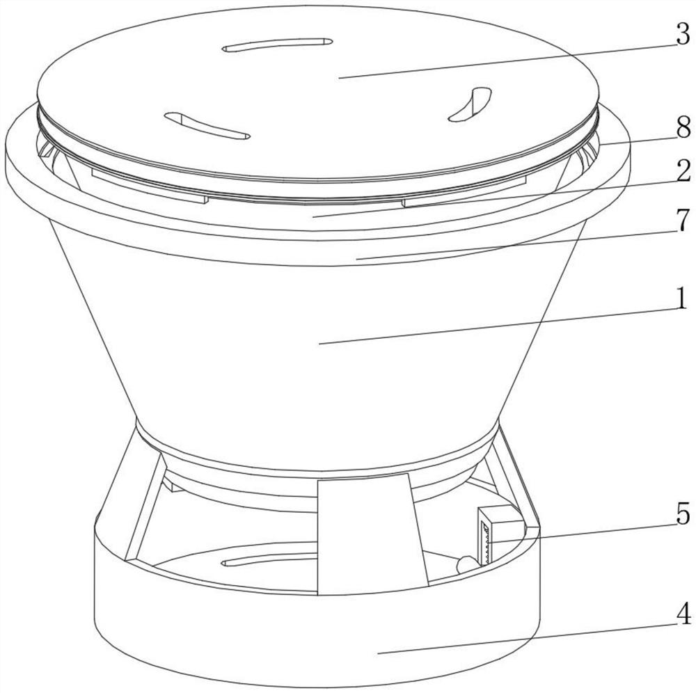
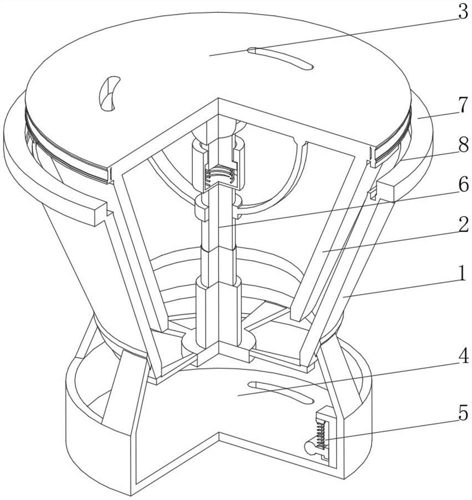
[0034] see Figure 1-Figure 4 , the present invention provides a technical solution: a municipal water conservancy project safety drainage cover with a warning function, which specifically includes:
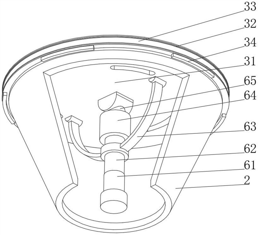
[0035] A conical outer cylinder 1, the inner wall of the conical outer cylinder 1 is slidably connected with a conical inner cylinder 2, and the top of the conical inner cylinder 2 is fixedly connected with a drain cover 3;
[0036] The water storage tank 4 is arranged below the conical outer cylinder 1 and is fixedly connected to the bottom of the conical outer cylinder 1 through a bracket. A control device 5 is arranged inside the box 4;
[0037] Lifting device 6, the lifting device 6 is arranged inside the conical outer cylinder 1, the lifting device 6 is fixedly connected to the inner wall of the conical outer cylinder 1 through a bracket, and the top of the lifting device 6 is fixedly connected to the bottom of the drainage cover 3;
[0038] A fixing ring 7, the fixing rin...
Embodiment 2
[0047] see Figure 1-Figure 5 , on the basis of the first embodiment, the present invention provides a technical solution: the control device 5 includes a control seat 51, a floating chute 52 is opened on one side of the control seat 51, and a floating rod 53 is slidably connected to the inner wall of the floating chute 52, and the floating rod A compression spring 54 is fixedly connected to the top of 53, and a pressure switch 56 is fixedly connected to one end of the compression spring 54 away from the floating rod 53. The top of the pressure switch 56 is slidably connected to the inner wall of the floating chute 52, and one end of the floating rod 53 extends to the floating chute 52. A float 55 is fixedly connected to the outside, the side of the control base 51 away from the floating chute 52 is fixedly connected to the inner wall of the water tank 4, the pressure switch 56 is electrically connected to the lifting platform 61, and one end of the floating rod 53 is fixedly c...
PUM
 Abstract
Description
Claims
Application Information
 - R&D Engineer
- R&D Manager
- IP Professional
- Industry Leading Data Capabilities
- Powerful AI technology
- Patent DNA Extraction
Browse by: Latest US Patents, China's latest patents, Technical Efficacy Thesaurus, Application Domain, Technology Topic, Popular Technical Reports.
© 2024 PatSnap. All rights reserved.Legal|Privacy policy|Modern Slavery Act Transparency Statement|Sitemap|About US| Contact US: help@patsnap.com


